Jari Honkanen, Director of Systems Engineering and Advanced Applications at Mic RoVision, introduced me to the amazing MEMS mobile mirror technology that MicroVision invented.
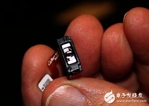
Figure 1: I have a single micro MEMS scanning mirror assembly in my hand.
At the end of 2016, MicroVision and STMicroelectronics announced a joint development, sales and promotion of laser beam scanning (LBS) technology. The two companies are currently using their LBS solutions to develop the pico projector and heads-up display (HUD) market, and the two companies are interested in further developing emerging markets and applications, including virtual reality and augmented reality (VR, AR), 3D inspection and Advanced Driver Assistance System (ADAS).
In addition, MicroVision and STMicroelectronics are also looking to explore solutions for future technology development, including the LBS product joint roadmap. These partnerships will fully integrate ST's process design and manufacturing expertise with MicroVision's LBS systems and solutions.
The industry is eager for laser radar technology for ADAS
This is a hot topic in the industry, and many big companies want to get a slice of it. Infineon acquired laser-specific technology through the acquisition of Innoluce last year. Analog Devices also acquired LBS technology from Vescent Photonics to support the popularity of mainstream automotive laser radar systems. I hope that there will be more similar acquisitions in the future, making this market hot.
Unique MicroVision MEMS Scanning Mirror Construction and How It Works
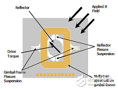
Figure 2: A mirror in the MEMS mirror assembly is suspended in a Gimbal Frame with a micromachined energized coil on the gimbal. Permanent magnets are mounted around the MEMS die to provide a magnetic field. By applying a current to the MEMS coil, a magnetic torque is generated on the gimbal and a component is produced in both directions of the axis of rotation.
A key feature of this design is that only one drive signal is input to the MEMS. In order to produce a two-axis movement, the vertical and horizontal movement of the waveform requires only a simple superposition.
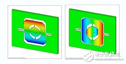
Figure 3: One component of the torque causes the gimbal to rotate about its flexure suspension (left); the other component excites the vibration of the mirror's resonant mode, causing the mirror to rotate around the flexure suspension of the gimbal (right).
This composite mirror drive waveform is a superposition of a 60 Hz vertical scan sawtooth wave function and a high frequency sine wave that excites the horizontal scanning resonance (Fig. 4).
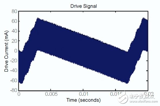
Figure 4: Composite drive waveform.
Position feedback for the two required scan angles is generated using a piezoresistive (PZR) strain sensor that is micromachined to achieve mirror deflection suspension and gimbal flexure suspension (Figure 5).
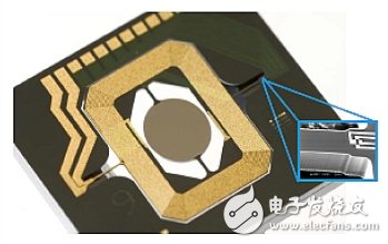
Figure 5: The MEMS scanning mirror die shown in the figure is in close proximity to the piezoresistive strain sensor for vertical scanning position feedback. The position system feedback signal can improve the stability of the projection display for a long time and under different environmental conditions.
Red, blue, and green laser diodes are integrated with MEMS scanning mirrors to form a compact color display engine, as shown in Figure 6. The scanning mirror system is designed using MEMS and small lasers, including the light source, with a total volume of no more than 5 cm3 and a height of only 6 mm.
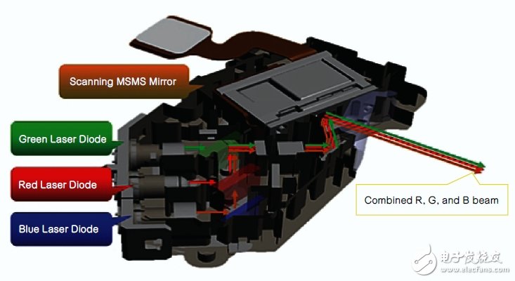
Figure 6: Scan engine subsystem including MEMS scanning mirror and laser source.
How PicoP laser beam scanning technology works
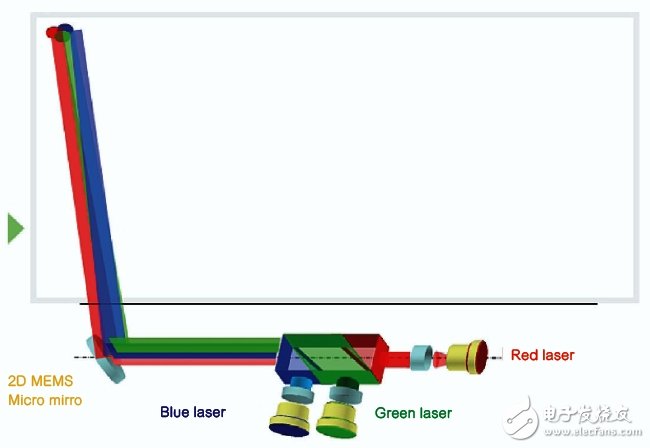
Figure 7: How PicoP scanning technology works.
When a single pixel of a certain color needs to be displayed, the laser in the system turns on. If one of the three lasers is not needed due to the image content, it can be turned off to minimize power consumption.
This system can produce 720p, 1280&TImes; 720 graphics display resolution, brightness up to 25lm, an image with a diagonal size of about 1m can be formed at a projection distance of 1.1m. Therefore, this design has the characteristics of low power consumption and small size. Another advantage of using a laser source is that the image is in focus at any projection distance point and does not require any adjustment. The use of a laser source also provides a wide color gamut to the display, producing vivid and vivid colors, such as the CIE chromaticity diagram in Figure 8.
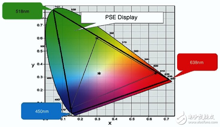
Figure 8: The laser source provides a wide color gamut and produces vivid colors.
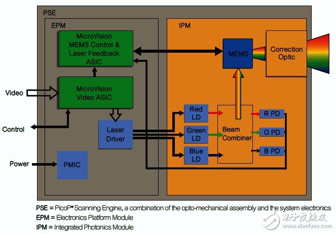
Figure 9: The display engine is integrated with the video and MEMS driver circuitry. This system forms the PicoP scanning engine.
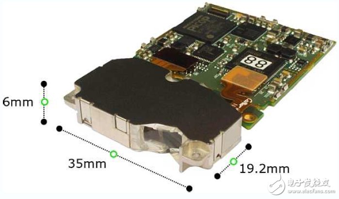
Figure 10: Engine based on MicroVision PicoP scanning technology. The device is much smaller than a coin, but its powerful ability to project an image onto any surface without distortion is amazing. It can also be used as an image capture device.
The scan engine consists of two units:
Integrated Photovoltaic Module (IPM)
Electronic Platform Module (EPM)
MicroVision's embedded solutions capture and process signals from data sources for controlling and synchronizing the color mixing and layout of individual pixels. By changing the intensity of each laser source, a complete palette of color gradients can be formed. A good example is the MEMS scanning mirror in a pico projector that directs the beam to the projection surface (Figure 11).
In head-up displays, specialized light components direct the beam to the optics outside the scanning engine so the driver can see the image directly in the forward field of view.
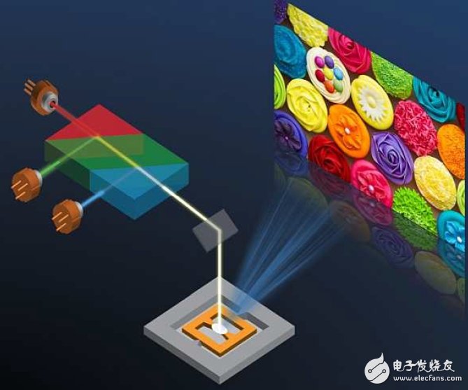
Figure 11: The red, blue, and green laser sources shown in the figure can produce almost all visible discernible colors. With such a light source, a MEMS scanner can produce a bright projected image that is always in focus.
HD image
To create vivid, high-definition images, this embedded solution arranges pixels by repeated horizontal and vertical scanning movements. This process can produce rich content without increasing form factor (device size) and power consumption (Figure 12).
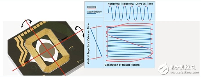
Figure 12: Horizontal and vertical scan movements for generating raster graphics.
MicroVision uses Honkanen's technology to project key information onto the car's windshield as part of the driving scene using a head-up display stack so that the driver's eyes can view the information without leaving the road (Figure 13). At the MEMS and Sensor Execution Conference, Honkanen demonstrated this application.

Figure 13: Example of a heads up display.
Honk anen also demonstrated how to develop a MEMS-based scanning lidar system using MicroVision's laser beam scanning technology with near-infrared (IR) lasers and infrared photodetectors.
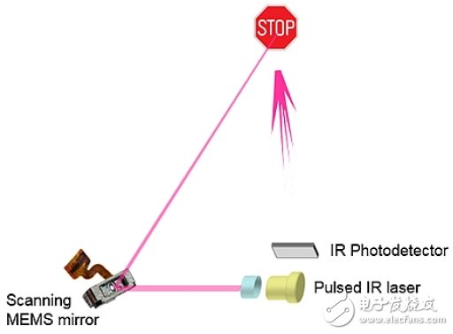
Figure 14: MEMS-based scanning lidar system.
The advantages of MEMS-based scanning lidar are high horizontal and vertical resolution, and the ability to dynamically change the detection resolution and frame rate. Depending on the application or driving situation, the same scanning lidar can achieve both slow and high resolution capture as well as fast, low resolution capture.
Energy Saving Sewing Machine Motor
Energy Saving Sewing Machine Motor,Single Sewing Machine Motor,Industrial Servo Motor,Single Phase Motor
LISHUI SHUANGZHENG MOTOR CO.,LTD. , https://www.szservomotor.com