Switching power supply is to use the circuit control switch tube for high-speed conduction and cut-off. The direct current ** is supplied to the transformer for high-frequency alternating current to be transformed, thereby generating a power supply of one or more sets of voltages required.
The switching power supply consists of the following parts:
First, the whole process of the main circuit from the AC grid input, DC output, including:
1. Input filter: Its function is to filter the clutter existing in the power grid, and also hinder the clutter generated by the machine from being fed back to the public power grid.
2. Rectification and filtering: The AC power supply of the power grid is directly rectified into a smoother DC power for the next level of transformation.
3. Inverter: The rectified DC power is changed into high frequency AC power, which is the core part of the high frequency switching power supply. The higher the frequency, the smaller the ratio of volume, weight and output power.
4. Output rectification and filtering: Provide stable and reliable DC power supply according to load requirements.
Second, the control circuit samples from the output side, compares with the set standard, and then controls the inverter to change its frequency or pulse width to achieve stable output.
Three conditions for switching power supplies
1, switch: power electronic device works in the switch state instead of the linear state
2, high frequency: power electronic devices work at high frequencies rather than near the low frequency of the power frequency
3, DC: switching power supply output is DC instead of AC
Switching power supplies mainly have the following characteristics:
1. Small size and light weight: Since there is no power frequency transformer, the volume and weight are only 20-30% of the linear power supply.
2. Low power consumption and high efficiency: The power transistor operates in the switching state, so the power consumption on the transistor is small, the conversion efficiency is high, generally 60 to 70%, and the linear power supply is only 30 to 40%.
The working principle of the switching power supply is:
1. The AC power input is rectified and filtered into DC;
2. The switching transistor is controlled by a high frequency PWM (Pulse Width Modulation) signal, and that DC is applied to the primary of the switching transformer;
3. The secondary of the switching transformer induces a high-frequency voltage, which is supplied to the load through rectification and filtering;
4. The output part is fed back to the control circuit through a certain circuit to control the PWM duty cycle to achieve the purpose of stable output.
When the AC power input is input, it generally passes through something like the Ericsson to filter out the interference on the grid and also filter out the interference of the power supply to the grid. When the power is the same, the higher the switching frequency, the smaller the volume of the switching transformer. However, the requirements for the switching tube are higher; the secondary of the switching transformer can have multiple windings or one winding with multiple taps to obtain the required output; generally, some protection circuits, such as no-load, short-circuit, etc., should be added. Otherwise it may burn the switching power supply.
Mainly used in industry and some household appliances, such as televisions, computers, etc.
Four basic types of single-chip switching power supply feedback circuits
(1) Basic feedback circuit;
(2) an improved basic feedback circuit;
(3) an optocoupler feedback circuit with a Zener diode;
(4) Optocoupler feedback circuit with TL431.
With the TL431 optocoupler feedback circuit, the circuit is more complicated, but the voltage regulation performance is the best. Here, the TL431 type adjustable precision shunt regulator is used to replace the ordinary voltage regulator tube to form an external error amplifier, and then the UO is finely adjusted, so that the voltage regulation rate and the load regulation rate are both ±0.2%, which can be linearly stabilized. The pressure power supply is comparable. This feedback circuit is suitable for forming a precision switching power supply.
Analysis of the main causes of damage to the switching power supply module:
1 The switching power supply module is not configured according to the actual DC load N+1 (the load current charging current is set to 10% of the rated capacity of the battery pack).
2 modules are often running at full load;
3 The reason for the current sharing of the system causes a module to be in full load operation;
4 The ambient temperature of the equipment room is too high;
5 The module filter is not cleaned regularly (the filter is too dirty and the module is stable, and the stacking temperature cannot be released in time);
6 Excessive dust in the module (due to the intrusion of dust. The hidden trouble caused by the accumulation), the air pump can be used to remove dust;
7 Harmonic effects.
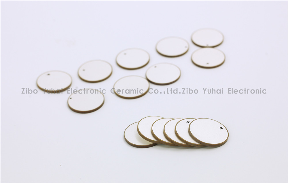
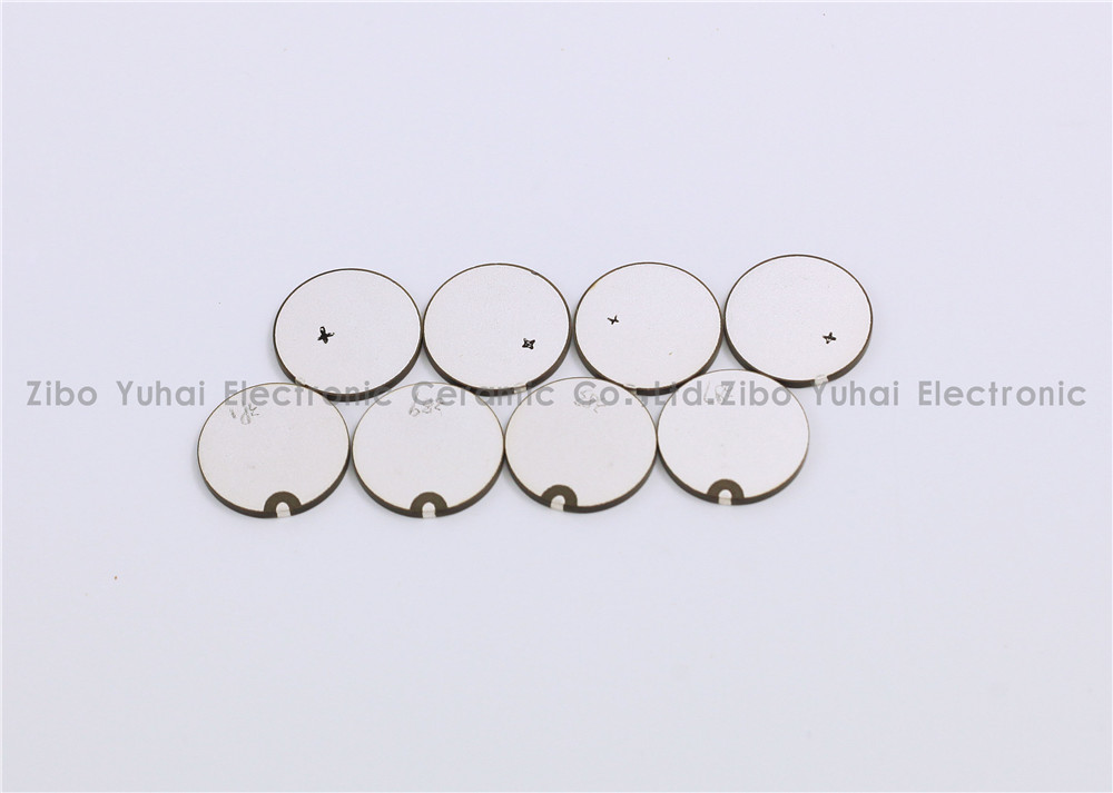
Piezoelectric Discs For Flowmeter Sensor
Piezoelectric ceramic disc
Quick delivery
High performance
Application: flow meter measurement
There are many kinds of USF used in closed pipeline according to the measuring principle, and the most commonly used are propagation time method and Doppler method. Among them, time difference ultrasonic flowmeter is used to measure fluid flow by the principle that the time difference of sound wave propagating downstream and countercurrent is proportional to the velocity of fluid flow. It is widely used in raw water measurement of rivers, rivers and reservoirs, process flow detection of petrochemical products, water consumption measurement of production process and other fields. According to practical application, time-difference ultrasonic flowmeter can be divided into portable time-difference ultrasonic flowmeter, fixed time-difference ultrasonic flowmeter and time-difference gas ultrasonic flowmeter.
Ultrasonic flow-meters use at least two transducers aligned so that ultrasonic pulses travel across the flow of liquid or gas in a pipe at a known angle to the flow.
Technical data:
Electromechanical coupling coefficient Kp: > 0.62
Dielectric Loss tg δ: <2%
Nominal Piezo discs for ultrasonic flowmeter:
OD14.2*1MHz PZT-51
OD14.6*1MHz PZT-51
OD15*1MHz PSnN-5
OD15*2MHz PSnN-5
OD20*1MHz PSnN-5OD20*2MHz PSnN-5
OD15*1MHz PZT-51
OD15*2MHz PZT-51
OD20*1MHz PZT-51OD20*2MHz PZT-51
Size, Frequency and Electrode on request.


Piezoelectric Ceramic Disc,Piezoelectric Disk Flow Meter,Piezoelectric Flow Sensor,Piezo Discs Flowmeter
Zibo Yuhai Electronic Ceramic Co., Ltd. , https://www.yhpiezo.com