The automobile tire pressure monitoring system (TPMS) can automatically monitor the tire air pressure in real time while the vehicle is running, and warn the tire leakage, low air pressure and high air pressure to ensure the safety of the driver and passenger [1]. The TPMS transmit antenna operates at a frequency of 433.92 MHz and has a signal transceiving distance of less than 10 m. It is mounted on the tire pressure detection module inside the tire. In order to ensure accurate and reliable data transmission when the vehicle is running, the antenna is required to have omnidirectionality. At the same time, because the installation space is limited, and the entire module is powered by only one lithium battery, the antenna is required to be small in size and high in emission efficiency. With the rapid development of TPMS, the research on miniaturized antennas is becoming more and more important on the basis of ensuring basic performance.
At present, the commonly used TPMS antenna types include inverted-F spiral antenna [2-3] and small-loop antenna [4]. The inverted-F spiral antenna has better performance but takes up a large space, while the small-loop antenna has a small volume but low emission efficiency. . In this paper, a small PCB spiral antenna was designed and fabricated according to actual needs, and was processed on a Teflon plate with an area of ​​only 20 mm & TImes; 16.7 mm. Compared with the conventional helical antenna, the PCB helical antenna has a large reduction in antenna size under the same total length. In addition, the metal wires are fixed on the PCB, and the parameters such as length, width and distance are easily controlled, so the antenna has a small size and is easy to manufacture. The experimental results show that the antenna can work at a frequency of 433.92 MHz and has good omnidirectionality to meet the performance requirements of the TPMS transmitting antenna.
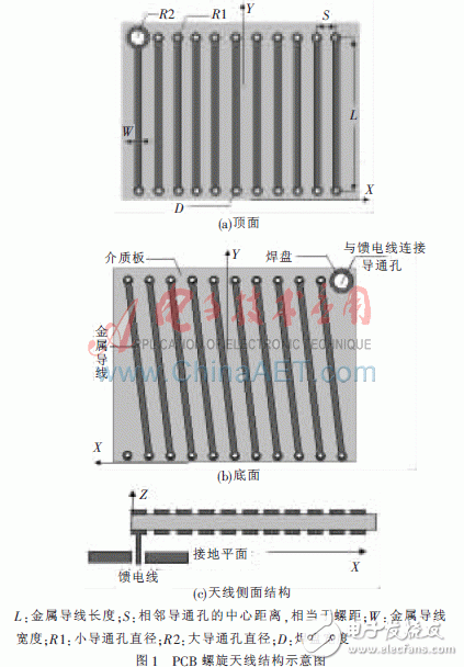
1 antenna structureThe structure of the PCB spiral antenna is shown in Fig. 1, and the antenna is composed of 11 turns of spiral. Metal wires are printed on both sides of the rectangular dielectric substrate, and have the same width, and have through holes at both ends, and the inner wall is covered with copper for connecting the two layers of metal. The feeder is connected to the largest via hole in the upper right corner of Figure 1(b), and the remaining via holes have the same diameter. In order to ensure the connection of the metal, in order to ensure the connection of the metal, a pad is added around each via hole in the design.

The operating frequency of the antenna depends on the size of the antenna itself. As can be seen from the structure of the antenna, the winding of such a helical antenna is very dense. According to the characteristics of the helical antenna, dense winding will produce parasitic inductance, resulting in an increase in the resonant frequency of the helical antenna [5], so the total length should be slightly shorter than the theoretical length in design.
This article uses the software CST MICROWAVE STUDIO for simulation. A dielectric substrate having a dielectric constant of 2.5 and a thickness of 1.6 mm was used. In order to meet the requirements of miniaturization, the minimum PCB process size needs to be selected during design. Therefore, according to the actual situation of the antenna fabrication, some parameters are fixed during the simulation, and the required frequencies can only be achieved by adjusting the parameters L and S.
Through the modeling and simulation of the antenna, the relationship between the antenna resonance characteristics and the metal wire length L and the pitch S is obtained, as shown in Table 1, where F is the center frequency. It can be seen from Table 1 that when S is constant, the resonant frequency decreases as L increases; when L does not change, the resonant frequency increases as S increases.

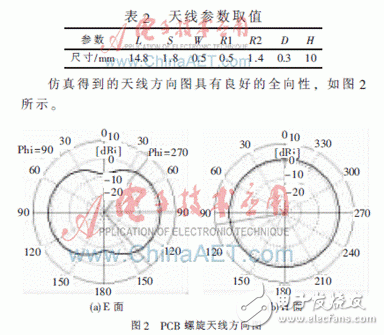
After optimization, the antenna parameters are designed as shown in Table 2.

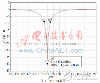
Since the antenna resistance is small, about 3.58 Ω, an external matching circuit is required to match the 50 Ω input impedance. In this paper, the T-type matching circuit is used to simulate in the software ADS, and the S11 curve is obtained as shown in Fig. 3. It can be seen from the figure that the effective working frequency band of the antenna is 432.6~435.2 MHz (S11<-10 dB). Although the bandwidth is narrow, the S11 at the operating frequency of 433.92 MHz is about -40 dB, which satisfies the conditions of signal transmission.

According to actual engineering experience, the loss of PCB board media has a great impact on the gain of the antenna. When the dielectric loss tangent is constant, the antenna gain decreases as the dielectric constant ε increases [6]. Therefore, a polytetrafluoroethylene dielectric plate with good stability and low loss is selected to fabricate the antenna. The dimensions of the antenna are 20 mm & TImes; 16.7 mm & TImes; 10 mm.
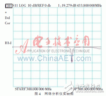
The measured S11 curve is shown in Fig. 4, which is basically consistent with the simulation results, which verifies the feasibility of the design. However, since the matching circuit is designed to use a self-made inductance, the processing accuracy is not high, and the measured S11 value is smaller than the simulation value. The effective bandwidth of the antenna is 432.2~435.3 MHz (S11<-10 dB), and S11<-15 dB at the frequency 433.92 MHz can be used as the signal transmitting antenna in the tire pressure detection module in TPMS. In practical applications, the matching circuit can use small, high-quality chip capacitors and inductors.

The TPMS transmit antenna operates at 433.92 MHz, has a low frequency, and is mounted inside the tire after being connected to other components. The space occupied is extremely small, which brings great difficulties to the design of the antenna. Aiming at this difficulty, this paper designed and fabricated a PCB spiral antenna and conducted experimental research. The results show that the antenna has good omnidirectionality, small size and light weight, which meets the needs of TPMS for miniaturization of the antenna. At the same time, the antenna of this structure has the advantages of simple manufacturing process, low cost, and easy integration with devices and circuits. However, due to bandwidth limitations, it can only be used as a fixed frequency transmit antenna. The receiving antenna in the TPMS needs to be designed separately.
Solar Inverter,Efficiency Home Inverter,Solar System Inverter,Solar Pump Inverter
GuangZhou HanFong New Energy Technology Co. , Ltd. , https://www.gzinverter.com