I classify the power amplifiers by themselves, not according to the working point, but according to the degree of difficulty. At present, the power amplifiers can be divided into broadband power amplifiers and narrow-band power amplifiers as shown in the following figure:
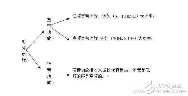
In fact, it can be classified into linear power amplifiers and non-linear power amplifiers. With the development of current digital modulation technology, the requirements for power amplifiers are also very demanding. Some are multi-carrier signals (OFDM). This requires stricter power amplifiers. Linear amplifiers must be used. At present, most of the linear power amplifiers made in China are power back. The efficiency of the power amplifier directly is very low, only about 10%, and I am currently developing it. Non-linear ones are better.
Many people are reluctant to do this kind of power amplifier. The radiation is too large, especially for those who are not married, women needless to say, even less, but it does not include no woman doing the power amplifier. influences. Haha. . . Everyone understands. . .
Then again, the profits of high-power amplifiers are also commendable. If you want to change your children's shoes for money, hurry and develop a high-power amplifier, you will definitely make money. . . .
To be honest, I am currently making a 50W power amplifier around 700MHz, and the power is not too large. This is also the first time I started to explore the high-power things. It used to be at 10W. I have a habit that is also bad. I do n’t particularly like to communicate with people. I always like to explore by myself. I feel that in today ’s society, you should explore by yourself. You are going to ask someone. Finally, some interests are involved. problem. Unless it is a very good friend. But I also don't like to ask. It's better to explore it by yourself. What you explore is always yours, and you will never forget it in your life.
Technical parameters of my amplifier (current version)
Frequency 750MHz --- 760MHz
Modulation method FM (CW wave)
Input power 0dbm
Gain 47db
Output power 47dbm (50W)
In-band flatness ± 0.5db
Stray -60dbc
P1dB > 47dbm
No filter for harmonic suppression, odd harmonics> 15dbc, even harmonics> 30dbc
IMD3 > -30dbc
Working voltage 28V (single power supply)
Current < 4A (actual debugging about 3.5A)
Power amplifier protection requirements
With gain adjustment function
PTT function
Standing wave protection function
Temperature detection and protection function
Forward power detection function
The above are specific technical indicators and requirements.
The following is the scheme I adopted. Some of the following involve commercial issues, which I will skip. Please understand that it is mainly to provide solutions for everyone. I will skip the specific layout and simulation. This is also an opportunity for everyone to play. If they are taken directly, they will be meaningless. My purpose is to work together This is the real purpose. For example, the indicator is put forward like this, how do you think about it!
Program:
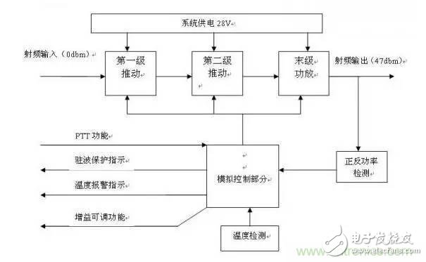
This is a block diagram of the entire power amplifier system. In fact, with this diagram, all power amplifiers are almost the same, but the power amplifier part is different. The rest is the same.
I use Freescale tubes, there are many, such as Infineon, NXP, ST, Fujitsu, many, many. I prefer to use Freescale's amplifier tube. This tube also provides ADS model, which is more convenient to use.
Next is my DIY start
I divided this amplifier into three stages, which are the debug version, the upgraded version, and the final version. Let me start with my debug version,
The debug version is relatively simple and is a separate module, mainly to verify whether it can be achieved. Can go directly to pcb. The result is that my debug version is very smooth is to pass the debug, the test results are as follows
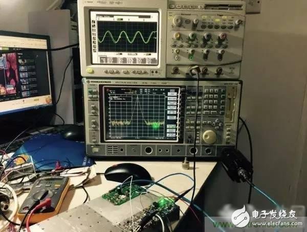
My workbench, three characters, dirty, messy, poor.
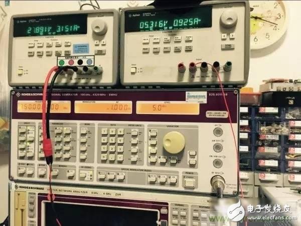
Input 5dbm, the gain is adjustable in front, the gain is different according to different voltages, now it is 5V control voltage.
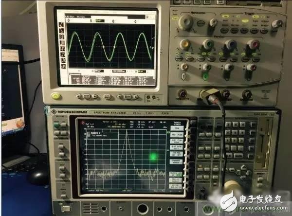
The output is 22.46dbm because there is a 25db attenuator in front of the spectrum analyzer. Calculate 25 + 22.46 = 47.46dbm after calculation, the output is 55.7W, so the debug version is basically ok! Wait for the upgraded version.
There is also an episode in the middle, I made a long time power, just 30 minutes. I pressed the heat block directly with my thumb, and the skin was directly whitened. . .

It doesn't seem to blow without a fan. . . . The upgraded version below must be blown with a fan. . .
Upgraded version
First proofing back
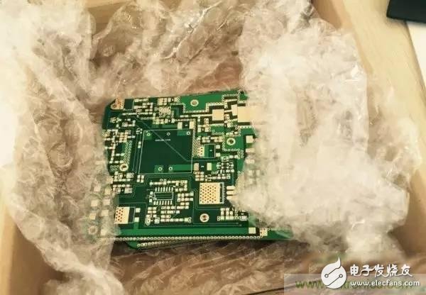
After working hard all night, the PCB was drawn. Although it is ugly, I will look at the debugging results first.
Next, consider the installation problem. Still re-tapping on the basis of the debug version. Just do it. . .
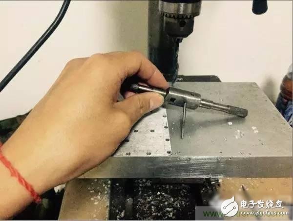
Drilling, tapping, see me, I can also work as an urgent fitter in the future, hahaha. . . .
Just right, perfectly suitable. The holes are not bad at all, the next step is to fill up the above devices.
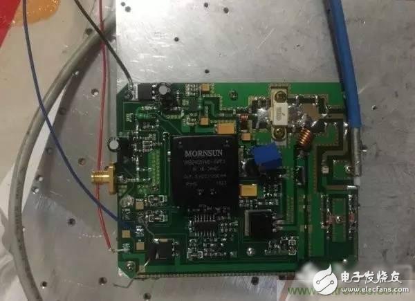
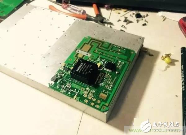
Upgraded version, complete functions after completing the device.
start testing
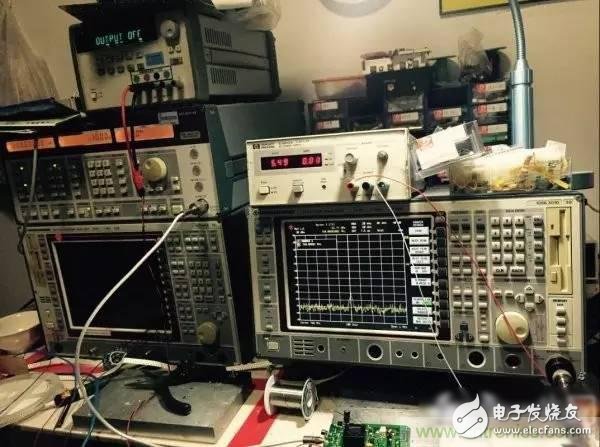
I can't figure it out, my workbench always has those three words ,,,,,,, hahaha. . . . . . .
Test Results
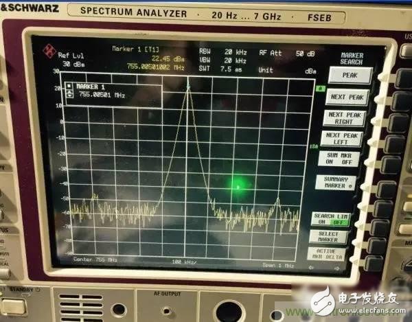
Test result 22.45dbm
The same spectrum analyzer input adds 25db attenuator,
25 + 22.45 = 47.45dbm (55W)
It seems that the upgraded version has also passed smoothly. It will be brought to the company tomorrow and tested with the company's instruments. (Secretly, everyone understands).
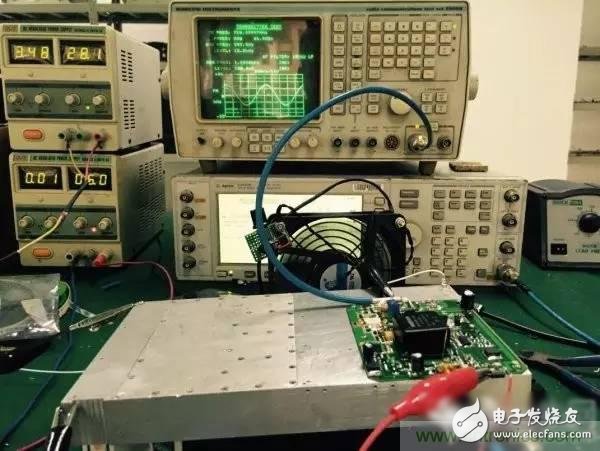
Test in company
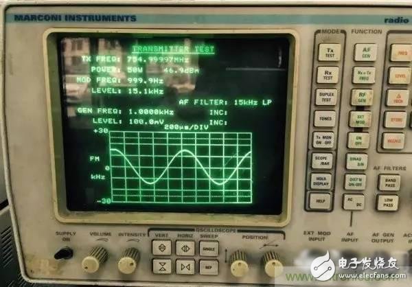
The final test result showed 46.9dbm (50W). This is different from the result of the previous test with a spectrum analyzer. It may be that the detection methods of the two instruments are different. So the test results are different (I guess). Either the instrument is different, and there is a slight difference of 0.4db. It is also possible that this instrument is relatively old. There is an error, this is not entangled, completely satisfied.
As for the other indicators behind, I will slowly test it, IMD3, and harmonics, etc., I will test later. There are also the functions I mentioned before, I have tested all of them, and they can all be realized. The high-power amplifier is mainly the standing protection function. I tested and opened the output of the amplifier, the control part immediately disconnected the power supply, and the standing wave The protection terminal outputs a high level to drive devices such as LEDs.
The temperature protection function is also realized. When the temperature reaches more than 70 degrees, the power amplifier will not work automatically, preventing the temperature from being too high to damage the power amplifier tube.
This time I used a big fan to keep blowing, and the effect is very good. I touched the heat sink, which is about 40 degrees (working for a long time).
So far, this amplifier has almost been realized, wait for the final version! ! ! Machining CNC makes an exquisite shell, people rely on clothes and horses, saddles, the same reason, with the cover of the cover, it will be more beautiful hahaha. . .
final version
Get dressed. . . . .
I feel pretty all by myself. . . .
This is the first time I have experienced this. I have gained a lot from doing high-power amplifiers, from the selection of the amplifier to the layout layout and simulation. As long as I study hard, I will definitely gain something. I believe that it is still willing to pay, and there will be rewards. If I do n’t pay, there will be no reward. I have also got angry in this product, and I even cried. I want to give up. When the level is promoted, the tube is always burned. I chose the tube of TriQuint Company. The tubes of this company are relatively expensive, so it is not a chip that is burned, it is money! ! ! . . . . . This is my hard salary. Burned 4 slices in a row. 600 yuan is gone, I really want to give up. Think about it the next day. Since you have done this, you must stick to it, then calm down and slowly adjust it, and finally stabilized. No matter what product or project, there are unknown sadness behind it. When you look at something very simple, you have to do it yourself to know that it is simple and easy.
To sum up, it is really too expensive to build high-power devices. My friend said that he is also working on power amplifiers with more than 2,000 tubes. Five were burned overnight. They are all caused by poor matching and long working hours. The high-power attenuator is big and scary, and the high-power amplifier has no harm to the body. The main thing is profit! ! !
Next, I will challenge the short-wave broadband power amplifier, such as 2--100MHz. 50W of power.
The difficulty of the power amplifier is that the gain is high and it will be self-excited, so the matching between the amplifier stages must be done, especially the end, the match must be done, otherwise the tube (money) will be burned. The current amplifiers are powered by 28V or 50V Therefore, the power supply must be set up so as not to turn on the power, and the power amplifier tube will be broken down. I have also encountered this.
Solving the above problem is: patience + time + experience = success
USB cables come in different shapes and sizes despite the fact a lot of them do the same things. In this short and handy guide, we`ll take a look at all the different types of USB cables available on the market and give you some examples of where you might find them in use.
USB Type-A, USB Type-B, Mini-USB, Micro-USB, USB-C
USB Cable,usb cable types,usb cable extension
ETOP WIREHARNESS LIMITED , https://www.oemwireharness.com