The eighth chapter is to understand AMetal in depth . The content of this article is 8.6 universal digital tube interface.
8.6 Universal Digital Tube Interface
> > > 8.6.1 Defining interfaces
1. Interface naming
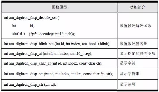
Since the object of operation is a digitron, the interface name is prefixed with "am_digitron_". The most common operation of the digital tube is to set the display content of the digital tube, and provide an interface for displaying characters and strings. The corresponding interface name is:
Am_digitron_disp_char_at
Am_digitron_disp_str
When displaying characters or strings, the digital tube can be displayed normally after decoding each character into the corresponding segment code. To do this, you need to provide an interface to set the decoding function, which is convenient for the user to customize the decoding function according to the actual digital tube, and then set it to the system through the interface. When a character needs to be displayed, the system first uses the decoding function to decode the character into a segment code. Its corresponding interface name is:
Am_digitron_disp_decode_set
In some applications, it may be necessary to display a special graphic. In this case, only the interface for displaying characters or strings is not enough. It is also necessary to provide an interface for directly displaying the segment code. The corresponding interface name is:
Am_digitron_disp_at
In addition, as a display, it is also necessary to clear all the contents displayed by the current digital tube, so that it is easy to reset the display content, and the corresponding interface name is:
Am_digitron_disp_clr
In particular, in addition to the operation related to setting the display content, the digital tube flashing display is required, and the corresponding interface name is:
Am_digitron_disp_blink_set
2. Interface parameter
Usually there are multiple digital tubes in the system, for example, using both MiniPort-View and MiniPort-ZLG72128. In a digital tube device, it may contain multiple digital tubes. For example, the MiniPort-View and the MiniPort-ZLG72128 both contain two digital tubes.
In order to distinguish different digital tube devices, each digital tube device needs to be assigned a unique ID. Based on this, the first parameter of all interfaces is set as the digital tube ID, which is used to specify the digital tube device to be operated.
The am_digitron_disp_char_at() interface is used to display one character. Although the digital tube device ID is used to determine the digital tube device that displays the character, the specific location displayed on the digital tube device cannot be determined only by the digital tube device ID. An index parameter is added to specify the position where the character is displayed. The valid range of the index is 0 ~ (the number of digital tubes - 1). If the MiniPort-View has two digital tubes, the valid range of the index is 0 ~ 1. In addition, the interface requires a parameter to specify the character to display. The function prototype that defines the interface is (the return value type is not defined yet):

For the am_digitron_disp_str() interface, which is used to display a string. In addition to the ID device ID, an index parameter is also required to specify the starting position of the string display. In addition, parameters are required to specify the string to be displayed and display. The length of the string. The function prototype that defines the interface is (the return value type is not defined yet):

Where len specifies the length of the display, p_str specifies the string to display, and the actual length displayed is the length of the string and the smaller of len.
For the am_digitron_disp_decode_set() interface, which is used to set the decoding function of characters, obviously, multiple digital tubes in a digital tube device are often the same, and the same decoding rule can be used to share a decoding function. Therefore, the interface only needs to specify the digital tube device by ID, and it is not necessary to use index to specify a specific digital tube index. The function of the decoding function is to decode the character, input a character, and output the code corresponding to the character. Based on this, the function prototype that defines the interface is (the return value type is not yet defined):

Where pfn_decode is a pointer to the decoding function, indicating the type of decoding function: a ch parameter with a 16-bit unsigned type, and a return value of 16-bit unsigned type encoding. This uses 16-bit data to represent characters and encodings for better scalability. In addition to the 8-segment digital tube, there are 14 segments of the m-shaped digital tube, 16-segment digital tube, etc. In these cases, the 8-bit data cannot represent the complete segment code.
For the am_digitron_disp_at() interface, it is used to directly set the displayed segment code, similar to displaying a character. In addition to the digital tube device ID, it is also necessary to use the parameter to specify the displayed position and the content to be displayed (segment code). The prototype of the interface is (the return value type is not defined yet):

For the am_digitron_disp_clr() interface, which is used to clear all the contents displayed by a digital tube device, it only needs to use the ID to specify the digital tube device to be cleared, without any additional parameters. The prototype that defines the interface is (the return value type is not defined yet):

For the am_digitron_disp_blink_set() interface, it is used to set the blinking property of the digital tube. In addition to the digital tube device ID, it is also necessary to use the parameter to specify the position of the digital tube that sets the blinking attribute and use the flashing attribute of this setting (on or off). , define the prototype of the interface as (temporary undefined return value type):

Among them, index specifies the position of the digital tube that sets the blinking attribute, blink specifies the blinking attribute, when the value is AM_TRUE, it flashes on; when the value is AM_FALSE, it flashes off.
3. return value
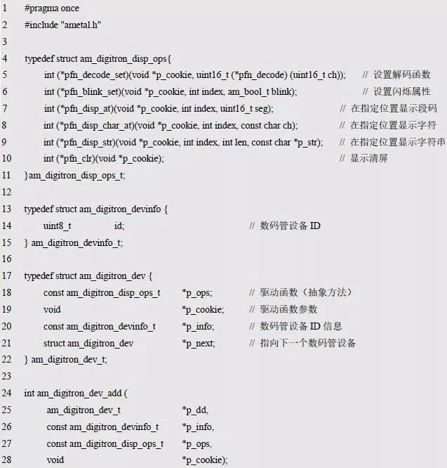
The interface has no special description, and directly defines the return value of all interfaces as the standard error number of type int. The complete definition of the digital tube interface is shown in Table 8.8. The corresponding class diagram is shown in Figure 8.16.

Figure 8.16 Digital tube interface
Table 8.8 Digital Tube Common Interface (am_digitron_disp.h)
> > > 8.6.2 Implementing the interface
1. Abstract digital tube equipment class
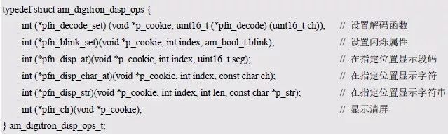
Similarly, the corresponding abstract method should be defined according to the universal digital tube interface to show the character function as an example. According to the previous general practice, the abstract method is defined as:

Compared to the generic interface, it adds a p_cookie parameter to point to the device itself. When defining the universal interface of the digital tube, the ID uniquely represents a digital tube device. It can be seen that here, both p_cookie and id refer to a certain digital tube device, because the abstract method is implemented by a specific digital tube device. , p_cookie is also used to point to the device itself. P_cookie has been able to uniquely identify a specific device. Therefore, the ID parameter has no practical use in the abstract method, and the ID parameter is removed from the abstract method, namely:

In fact, it can be seen that the parameter is changed from an abstract meaning ID (only a number) to a meaningful p_cookie (a pointer to the device itself).
Based on this, according to other general-purpose digital tube common interfaces, they define the corresponding abstract methods one by one and store them in a virtual function table, namely:
Readers may find that when implementing the LED interface, the defined abstract method contains both the p_cookie and led_id parameters. which is:
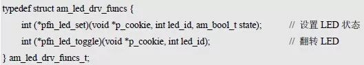
This is because in the design of the general LED interface, the ID is not the number of the LED device, but the number of all the LEDs in the system. For example, the AM824-Core has 2 LEDs onboard and 8 on the MiniPort-LED. LEDs, if they are used at the same time, there are two LED devices in the system, but there are a total of 10 LEDs with LED numbers 0~9. Therefore, although p_cookie is able to determine which LED device to operate, it is still not possible to determine the specific LED to operate. Therefore, the LED number must be passed as a parameter to the specific method for accurate operation to a specific LED.
In the design of the universal digital tube interface, ID is the number of the digital tube device. If the MiniPort-View and MiniPort-ZLG72128 are used at the same time, there are two digital tube devices in the system. Although there are 4 digital tubes in total, the digital tube The device number will only be 0~1. Because of this, the digital tube device ID does not contain the location information of the specific digital tube. In order to display the display content to a certain digital tube, an additional index parameter is required.
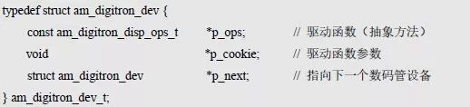
Similarly, the abstract method and p_cookie are defined together, which is an abstract digital tube device. such as:
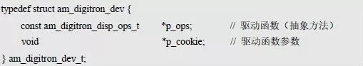
Similar to the LED abstract device, there may actually be multiple digital tube devices. Since their specific number cannot be predetermined, the unidirectional linked list is used for dynamic management. Add a p_next member to am_digitron_dev_t to point to the next one. equipment. which is:
At this time, a plurality of digital tube devices in the system are managed in the form of a linked list. Because in the common interface, id is used to distinguish different digital tube devices. Therefore, in the implementation of the universal interface, it is necessary to be able to find the corresponding digital tube device by the ID number in order to use the abstract method therein. Similar to the LED device, you can bind a digital tube device and the ID information corresponding to the device, and you can find the corresponding digital tube device by ID.
A digital tube device corresponds to a unique ID, and the type of the digital tube device ID information can be defined as:

A p_info pointer to the ID information is added to the device to facilitate the discovery of the corresponding digital tube device based on the ID in the general interface implementation, namely:

Based on this, the implementation of the am_digitron_disp_char_at() function is detailed in Listing 8.44.
Listing 8.44 am_digitron_disp_char_at() interface implementation example
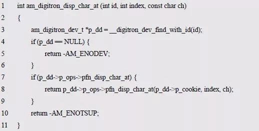
Among them, the role of __digitron_dev_find_with_id() is to traverse the device list and compare it with the ID information in each device to find the digital tube device corresponding to the digital tube ID. For details, see Listing 8.45.
Listing 8.45 Finding a digital tube device with the specified id
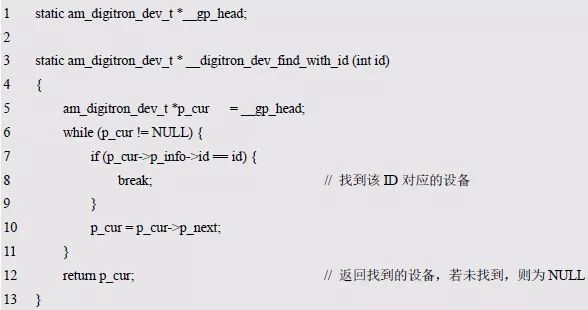
Among them, __gp_head is a global variable, pointing to the list header of the digital tube device, initially NULL, indicating that there is no digital tube device in the system at the beginning. Similarly, the implementation of other interfaces can be obtained. For details, see Listing 8.46. Their implementations are very similar. First, the IO_device corresponding to the ID is found by the __digitron_dev_find_with_id() function, and then the abstract method in the device is directly called.
Listing 8.46 Example of implementation of other digital tube interfaces

Since there is currently no digital tube device, the return value of __digitron_dev_find_with_id() is always NULL, so that the return value of the generic interface is always -AM_ENODEV (error: no such device).
In order for the universal interface to operate to a specific and effective digital tube device, an effective digital tube device must be added to the system before using the universal digital tube interface. According to the definition of the digital tube device type, when adding a device, you need to complete the correct assignment of p_ops, p_cookie and p_info. The values ​​of these members are implemented or defined by the specific digital tube device. For this reason, it can be driven by the device of the specific digital tube. Provide an interface to add a digital tube device, define its function prototype as:
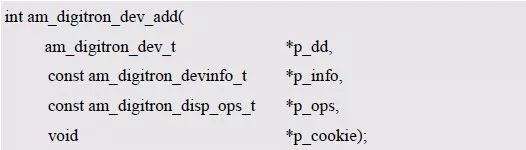
In order to facilitate the direct addition of a device, to avoid directly operating each member of the digital tube device, the members that need to be assigned are passed to the interface function through parameters. The implementation is detailed in Listing 8.47.
Listing 8.47 Adding a Digital Tube Device to the System

First check the validity of each parameter, and then use the __digitron_dev_find_with_id() function to determine whether the ID number of the new device is already in the system. If the ID already exists in the system, the addition fails, and the direct return operation does not allow the error (-AM_EPERM). . If the ID does not exist in the system, continue to execute to ensure that the IDs of the added digital tube devices do not conflict, ensure the uniqueness of the digital tube device number, and then assign the values ​​of each member in the device. Finally, through the program list 8.47 17~18 These 2 lines of code add new devices to the list header.

Figure 8.17 Abstract digital tube device class
Obviously, the next step is to implement the corresponding abstract method in the specific digital tube device, and then use the am_digitron_dev_add() interface to add the device to the system, so that the user can use the digital tube universal interface to operate to a specific effective digital tube. For ease of reference, the contents of the nixie device interface file (am_digitron_dev.h) are shown in Listing 8.48.
Listing 8.48 am_digitron_dev.h file contents
2. Specific digital tube equipment
Take the MiniPort-View driven by GPIO as an example to describe the implementation of the specific digital tube device. First, a specific device class should be derived based on the abstract device class. The class diagram is shown in Figure 8.18. The specific digital tube device class is defined as follows:

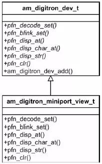
Figure 8.18 Specific digital tube equipment class
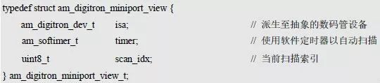
Am_digitron_miniport_view_t is a specific digital tube device class. With this type, you can use this type to define a specific instance of the digital tube device, namely:

For the dynamic scanning type of digital tube, the segment code displayed by the digital tube needs to be buffered into a piece of memory, and then periodically scanned, sequentially scanning each digital tube, taking out the segment code of the current scanning digital tube from the buffer, and then transmitting the segment code to Displayed on the corresponding pin.
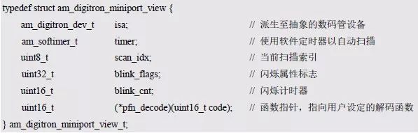
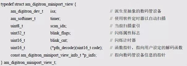
In order to realize the automatic scanning of the digital tube timing, a software timer is needed, and a software timer timer member can be added; during the scanning process, the current scanning position needs to be recorded in real time, so as to retrieve the corresponding segment from the corresponding digital tube buffer. Code, after scanning a digital tube, the scanning position should be updated to the position of the next digital tube. You can add the scan_idx member to store the current scanning position of the current digital tube in real time. That is, the device type can be defined as:
In addition, in order to save the flicker attribute, a member of the blink_flags can be added to indicate the blinking attribute of each digital tube. When the value of a bit is 1, it indicates that the corresponding digital tube needs to blink. In a blinking period, it needs to be lit for a period of time, and needs to be extinguished for a period of time. In order to determine what state should be in the current state, a flashing timer member, blink_cnt, can be added for timing in one blinking period. In particular, in the general interface, there is an interface for setting the digital tube decoding function. In order to decode the characters using the decoding function set by the user when displaying characters, a function pointer is needed to save the decoding function set by the user, based on Thus, the device type can be defined as:
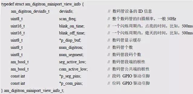
In addition, in order to use the digital tube normally, it is also necessary to know some basic hardware-related information, such as: bit selection pin information, segment code pin information, number of digital tubes, number of segment codes, etc., according to which, the digital tube device can be defined. The type of information is:

At the same time, for the dynamic scanning type digital tube, a buffer is needed to store the displayed segment code. The size of the buffer should be the same as the number of the digital tube. A p_disp_buf pointer can be added to point to the corresponding buffer. In addition, when the digital tube is dynamically scanned, the scanning frequency must be greater than 25 Hz, so that the process of dynamic scanning can not be seen by the naked eye, so that the display of the entire digital tube is complete and smooth. Obviously, the higher the frequency, the faster the scan, the smoother the display, but the more CPU resources are used when scanning the digital tube; the lower the frequency, the less CPU usage of the system, but not too low. To do this, you can add a scan_freq member to the device information to specify the frequency of the scan so that the scan frequency can be configured by the user according to the actual situation. The scan frequency directly determines the period of the timer scan. If the scan frequency is 50Hz, the time for scanning the digital tube is 20ms. Since there are two digital tubes in the MiniPort-View, the timer scan period is 10ms. It can be seen that the time interval of the timer timing scan is: 1000 / scan_freq / digitron_num.
In addition, when the digital tube needs to flash, in order to more personalized custom flicker effect, you can use blink_on_time and blink_off_time to specify the time of lighting and the time of extinction in a blinking cycle, respectively, and the sum of their times is the blinking period. The frequency of the flashing.
At the same time, in the universal interface of the digital tube, each digital tube device uses the ID number to distinguish. Obviously, this requires assigning a unique ID to the specific digital tube device, and a member dev_info indicating the ID information can be added to the device information. The type of complete digital tube device information is defined as:
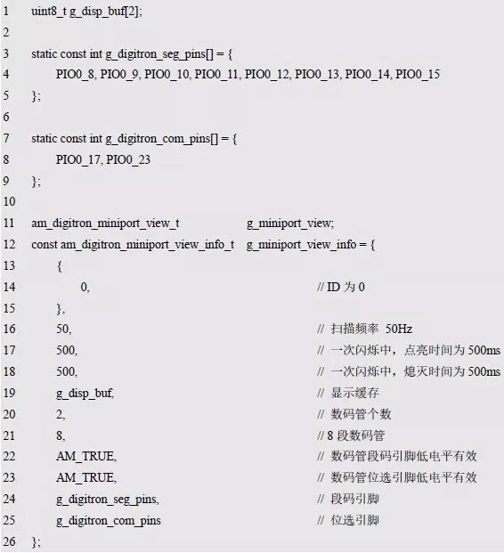
When the AM824-Core is used in conjunction with the MiniPort-View, if the ID number assigned to the digital tube device is 0 and the scanning frequency is 50 Hz, the LED will be on and off for one flashing period. 500ms, based on the equivalent circuit diagram and digital tube information, define the device instance information corresponding to MiniPort-View as:
Similarly, in the device type of the digital tube, it is necessary to maintain a pointer to the digital tube device information, so that the relevant information can be taken out from the digital tube device at any time. The complete digital tube device type is defined as:
In the actual development process, the structure type of the device or device information is usually not completely defined at one time. After the basic structure is defined, in the process of implementing each abstract method, the members are added as needed, and the structure is continuously improved. The definition of the body type.
In order to scan the digital tube normally, it is necessary to complete the assignment of each member in the device. After the initial assignment is completed, the software timer can be started, and the digital tube is automatically scanned at the scanning frequency specified in the device information. This work is usually done in the driver's initialization function, and the prototype that defines the initialization function is:

Where p_dev is a pointer to an instance of the am_digitron_miniport_view_t type, and p_info is a pointer to the instance information of the am_digitron_miniport_view_info_t type, which is called as follows:

After the initialization is completed, you can use the universal digital tube interface to operate the digital tube device numbered 0. The implementation example of the initialization function is shown in Listing 8.49.
Listing 8.49 Initialization Function Implementation Example
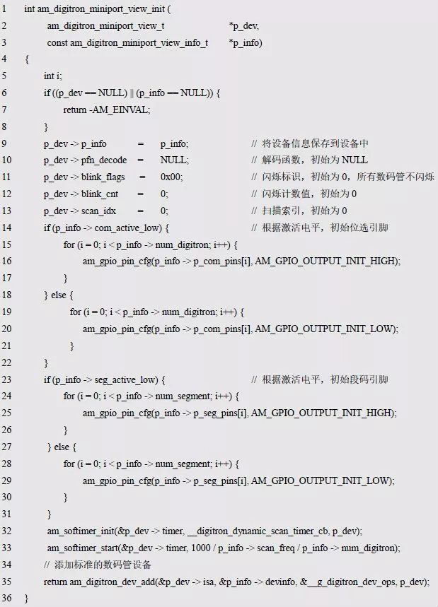
The program first checks the validity of the parameters, then completes the initial assignment of each member of the device, and then configures the bit select and segment code pins to output based on the activation level of the bit select pin and the segment code pin. Mode, and set the initial level to the inactive level so that the nixie is initially fully extinguished.
Then, the software timer is initialized and started, and the timing period of the software timer is set according to the scanning frequency. The periodic callback function of the software timer must be set to __digitron_dynamic_scan_timer_cb(), that is, the digital tube scanning is completed in the function. . Finally, use the am_digitron_dev_add() interface to add the device to the system, and use the ID number information as the argument of the interface p_info, &__g_digitron_dev_ops as the argument to the interface p_ops, point to its own pointer p_dev as the argument to the interface p_cookie , __g_digitron_dev_ops contains the implementation of each abstract method.
It can be seen that the key to implementing the entire digital tube device is to complete the digital tube scanning in __digitron_dynamic_scan_timer_cb() and implement the abstract methods in __g_digitron_dev_ops.
The implementation of the timer callback function __digitron_dynamic_scan_timer_cb() is detailed in Listing 8.50.
Listing 8.50 Implementation of the timer callback function (digital tube scan)

The program first processes the flicker timer. If there is a flashing digital tube, the flicker timer p_dev->blink_cnt is added, and the added value is the scan time interval. In particular, if the value exceeds the blinking period after the increase, it returns to 0. Then use __scan_seg_send() to send the phantom segment code and __scan_com_sel() to process the bit selection. If the current digital tube needs to be displayed normally, that is, the current digital tube does not need to flash, or if it needs to blink, but according to the flashing timer, it is determined that the current time is in the time period of lighting the digital tube, the segment of the current digital tube is taken out from the display buffer. Code and send it out using __scan_seg_send(). Finally, the value of the scan position index scan_idx is updated so that the next digital tube can be scanned for the next scan. The implementation of the segment code transmission function and the bit selection function is shown in Listing 8.51.
Listing 8.51 Implementation of the segment code send function and bit select function

Next, we need to implement a total of six abstract methods in the abstract digital tube device to complete the definition of __g_digitron_dev_ops.
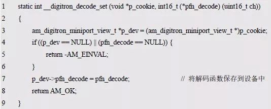
Pfn_decode_set
This method is used to set the decoding function to facilitate decoding of each character when displaying. Obviously, you need to save it to your device for later use. The sample program is detailed in Listing 8.52.
Listing 8.52 Example of setting up a decoding function implementation program
Pfn_blink_set
This method is used to set the blinking property of a digital tube. When setting the blinking attribute, you only need to set the corresponding position of the flashing flag blibk_flags in the device to 1 (flashing) or clear (not flashing). For the sample program, see the program list. 8.53.
Listing 8.53 Setting an implementation example program for the blinking property function

Pfn_disp_at
The method is used to display the specified segment code graphic on the designated digital tube, and only needs to store the segment code in the digital tube buffer. The sample program is shown in Listing 8.54.
Listing 8.54 shows an example program for implementing the segment code function
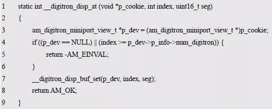
The program calls the __digitron_disp_buf_set() function to set the segment code to the cache, as shown in Listing 8.55.
Listing 8.55 __digitron_disp_buf_set() function implementation

The program determines whether the segment code set by the user needs to be inverted and stored in the buffer according to the activation level of the digital pipe segment.
Pfn_disp_char_at
This method is used to display characters at a specified position. This requires first using the decoding function to get the segment code corresponding to the character, and then setting the segment code to the buffer. See Appendix 8.26 for the sample program.
Listing 8.56 shows an example program for implementing a character function

The program first obtains the segment code of the character in the seg through the decoding function. The segment code is then saved to the corresponding buffer, and the decimal point is specially processed when the segment code is saved.
When the character is a decimal point, the segment code is set to the function area using the __digitron_disp_buf_xor() function; otherwise, the segment code is directly set to the buffer area using the __digitron_disp_buf_set() function.
Since the decimal point is special, when displaying the decimal point, it is often undesirable to affect the normal display content of the digital tube. For example, if the current digital tube displays the number 3 and needs to add a decimal point to the digital tube, the desired result is displayed. 3.", instead of just displaying a decimal point, overwrite the previous 3. It can be seen that when displaying the decimal point, it can be regarded as a superposition of the display content, instead of directly changing the display content, the implementation of the __digitron_disp_buf_xor() function is shown in Listing 8.57.
Listing 8.57 __digitron_disp_buf_xor() function implementation

If the digital pipe segment is activated at a low level, it is necessary to clear the segment indicating the decimal point to be lit on the basis of the original buffer segment code to display the decimal point; otherwise, the segment to be illuminated with the decimal point is set to 1 to display Decimal point.
Pfn_disp_str
This method is used to display a string starting from the specified location. The sample program is shown in Listing 8.58.
Listing 8.58 String Display Function Implementation Sample Program
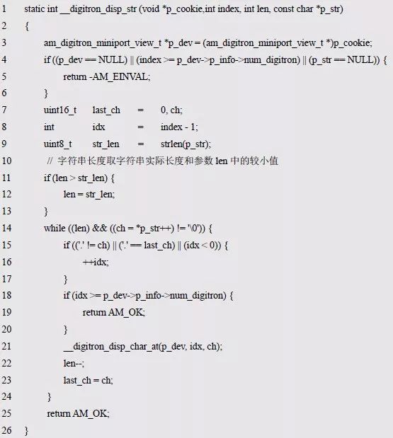
The program first determines the length of the string, the length of the string takes the actual length of the string and the smaller value in the parameter len, and then in the while loop, the __digitron_disp_char_at() function is called to display a single character in turn.
The idx is used to specify the display position. The initial value is index – 1, that is, the last digit position of the string display start position. If the start position is 0, the initial value of idx indicates an invalid position. You need to update the value of idx (add idx to 1) before displaying new content. However, in a special case, the decimal point does not need to update the display position. For example, the display string "3.5", the effect of the desired display is to occupy only 2 digital tubes, respectively displaying "3." and "5" instead of occupying 3 digital tubes. In this case, when the decimal point is displayed, it can be directly displayed in the digital tube where “3†is located, and it is not necessary to display it separately to a digital tube. The conditions under which the program needs to update the display location are:
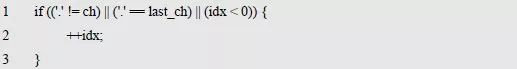
It can be seen that the condition that does not need to update the location is the opposite of the above conditions:
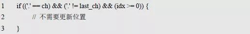
The condition for not updating the position is: the currently displayed character is a decimal point, and the previous character is not a decimal point, and the display position specified by idx is valid.
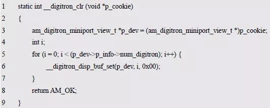
Pfn_clr
This method is used to clear the digital tube display, and all the contents of the buffer need to be set to the extinction segment code. The sample program is shown in Listing 8.59.
Listing 8.59. Example of clearing the implementation of the display content function
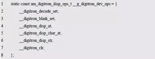
At this point, the implementation of each abstract method, based on the implementation function of each abstract method, the definition of __g_digitron_dev_ops is detailed in Listing 8.60.
Listing 8.60 Definition of __g_digitron_dev_ops
When the user uses the initialization function to complete the initialization of a specific digital tube device, the universal digital tube interface can be used to operate the digital tube to display the specific content. However, you must use the generic interface to set a decoding function before displaying characters or characters. For 8-band digital tubes, the segment code for each ASCII character can be defined in an array and then a decoding function can be implemented. See Listing 8.61 for details.
Listing 8.61 Implementation of the decoding function
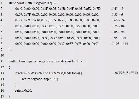
Based on this, before the user uses the nixie interface to display characters or strings, the decoding function can be set to the system using the interface that sets the decoding function for correct decoding. such as:

If the user needs to customize a decoding function before using the digital tube every time, it is very troublesome. For the 8-segment digital tube, the display method of the common graphic is fixed, and the corresponding segment code can be determined, such as the number 0 ~ 9. If the user does not have special requirements, the decoding function shown in Listing 8.61 can satisfy most applications. Based on this, the decoding function shown in Listing 8.61 can be defined in the system and used directly by the user. For the convenience of the user, the decoding function can be declared in the digital tube interface file.
For ease of reference, the contents of the specific digital tube device (MiniPort_View) interface file (am_digitron_miniport_view.h) are shown in Listing 8.62.
Listing 8.62 am_digitron_miniport_view.h file contents

Bacteria are everywhere in our daily lives. Mobile phones have become an indispensable item for us. Of course, bacteria will inevitably grow on the phone screen. The antimicrobial coating used in our Anti Microbial Screen Protector can reduce 99% of the bacterial growth on the screen, giving you more peace of mind.
Self-healing function
The Screen Protector can automatically repair tiny scratches and bubbles within 24 hours.
Clear and vivid
A transparent protective layer that provides the same visual experience as the device itself.
Sensitive touch
The 0.14mm Ultra-Thin Protective Film can maintain the sensitivity of the touch screen to accurately respond to your touch. Like swiping on the device screen.
Oleophobic and waterproof
Anti-fingerprint and oil-proof design can help keep the screen clean and clear.
If you want to know more about Anti Microbial Screen Protector products, please click Product Details to view the parameters, models, pictures, prices and other information about Anti Microbial Screen Protector products.
Whether you are a group or an individual, we will try our best to provide you with accurate and comprehensive information about Anti Microbial Screen Protector!
Antimicrobial Screen Protector, Anti-microbial Screen Protector, Anti-bacterial Screen Protector, Antibacterial Screen Protector,Anti-microbial Hydrogel Screen Protector
Shenzhen Jianjiantong Technology Co., Ltd. , https://www.jjthydrogelprotector.com