In modern industrial control systems, the 4-20 mA current loop transmitter has been the most commonly used transmitter for data transfer between the control center and the field sensor/actuator, primarily for ease of installation, use and maintenance. As pneumatic signals were used to control actuators and as proportional control in early industrial automation sites, 4-20 mA current loop transmitters began to be used in large numbers [1]. Typical pressure ranges are 3 PSI – 15 PSI, with 3 PSI representing zero input/output and 15 PSI representing full input/output. If the pneumatic line breaks, the pressure will drop to 0 PSI, indicating a fault that needs to be repaired. After the popularity of electronics began, pneumatic lines were gradually replaced, replaced by 4-20 mA current loops consisting of amplifiers, transistors and other discrete electronic components.
You might ask "Why use a current loop?" Kirchhoff's law states that the current is constant in a closed loop. This allows a 4-20 mA current loop to be used over long distances, and the current at any point in the loop is constant, independent of the lead resistance. Of course, the premise of the validity of Ohm's law is to have sufficient loop voltage. Similar to a pneumatic system, a broken or disconnected line reduces the loop current to 0 mA and the fault must be repaired. In addition, the current loop can also relatively easily prevent damage caused by electrical transients, and also has natural resistance to radio frequency interference or electromagnetic interference [2].
The most common 4-20 mA transmitter type is a two-wire topology or a two-wire sensor transmitter (see Figure 1).
Figure 1 Simplified two-wire 4-20 mA sensor transmitter with two-wire analog input module
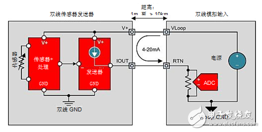
A two-wire sensor transmitter is used to send physical parameters of the field back to the analog input module for processing and control. Physical parameters include pressure, position, temperature, level, strain, load, flow, composition/impurities, and the like. As with the product name, the transmitter is a two-wire. Therefore, the sensor's power line is the same as the two lines that carry the 4-20 mA signal, which is the primary design requirement for a two-wire 4-20 mA transmitter. The operating current of the sensor, sensor conditioning circuit, and 4-20 mA transmit circuit must be less than 4 mA or the transmitter will not be able to output a 4 mA zero level [3].
Note that VLOOP GND is not the wiring for the two-wire transmitter. Therefore, the transmitter must create a local ground (GND) or two-wire GND. When the transmitter output current changes the voltage at the receiver impedance return (RTN) connector, the two-wire GND must float up and down relative to VLOOP GND [3]. If the sensor can be electrically connected to the potential relative to VLOOP GND, then isolation is required. This situation is more common in thermocouple sensor transmitters because thermocouples are typically thermally shorted or electrically shorted to the material at which they are measured.
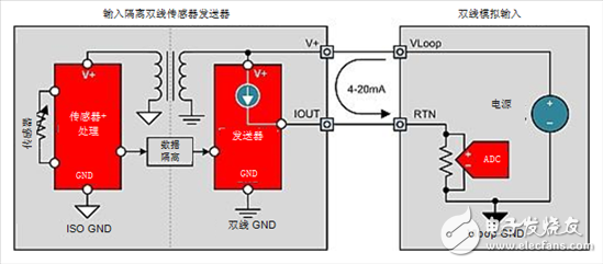
The two-wire transmitter has only one possible isolation topology: the input isolation two-wire transmitter (see Figure 2). The input isolated two-wire transmitter generates a partially isolated power supply from the ring power supply that supplies power to the sensors, sensor conditioning circuitry, and isolated communications. The most common method of data transfer between the isolation barrier and the transmitter output stage is digitally isolated wide pulse modulation, single line or serial peripheral interface (SPI) signals.
Figure 2 Simplified Input Isolation Dual Line 4-20 Ma Sensor Transmitter
As mentioned above, the two-wire sensor transmitter has certain limitations, mainly because the total current consumption of the sensor transmitter must be less than 4 mA. This means that many types of sensors are not available, including low-resistance bridges that do not limit bridge current (eg 100 Ω, 120 Ω, 350 Ω) as they reduce the sensitivity and accuracy of the bridge. The three-wire sensor transmitter topology (see Figure 3) supports sensor transmitter designs with operating currents in excess of 4 mA.
Figure 3 Simplified three-wire 4-20 mA sensor transmitter (two-wire analog input module)
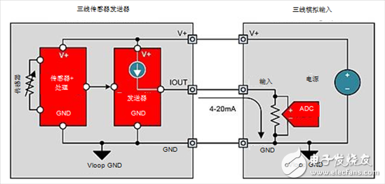
The three-wire sensor transmitter receives power from the three-wire analog input module and is connected to GND to support the power requirements of the sensor and conditioning circuitry. This allows the sensor power to reach the required level without affecting the sensor's output range (keeping Ohm's law). This also allows the three-wire transmitter to create common output current ranges such as 0-20 mA and 0-24 mA. A three-wire sensor transmitter is also used when a voltage output is required (eg 0-10 V, ±10 V).
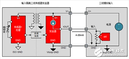
If the sensor must be isolated from the analog output module supply and the GND potential, the three-wire transmitter also has an isolation topology: the input isolating three-wire transmitter. The isolation structure of the input isolated three-wire transmitter is similar to the input isolation two-wire transmitter. A partial isolated supply of power is generated for the sensor and sensor conditioning circuitry before the sensor information is sent to the three-wire transmitter output stage via the isolation barrier.
Figure 4 Simplified Input Isolation Three-Wire Sensor Transmitter
in conclusion
Although the 4-20 mA current loop transmitter has been around for decades, it is still widely used in industrial plant automation and control applications. Field-level two- and three-wire sensor transmitters occupy most of the market share of the analog input logic market for analog three-wire programmable logic controllers (PLCs), while the rest are occupied by four-wire sensor transmitters.
In the next issue we will discuss how accurate current measurement optimizes motor control, and you are welcome to continue to pay attention.
references
4-20 mA Transmitter Application Note, Dataforth Corporation.
Duke, Kevin. Industrial DACs: How to Protect Two-Wire Transmitters, Analog Precision Technology, Texas Instruments, 2015.
Wells, Collin. Dual Line 4-20 mA Sensor Transmitter Blog Series, Analog Precision Technology Talk, Texas Instruments, 2015.
Author: Collin Wells, Texas Instruments Precision Analog Applications Engineer
Thermal printers are more smaller, lighter and consume less power, making them handheld Thermal Printer. Thermal printers are perfect mobile printer. Commercial applications of thermal printers include express, manufacturing, finance, ticketing, enforcement, warehouse, retail, parking and etc. Below is our advantages:
1. Mobile Bluetooth Printer, handy and stylish
2. USB/Bluetooth/RS232 various interface
3. Support label printing and receipt printing
4. Support Android/IOS/Win/Win CE/Symbian systems
5. High speed printing and high compatibility

Thermal Printer
Thermal Label Printer,Thermal Receipt Printer,Thermal Transfer Printer,Bluetooth Thermal Printer
Shenzhen Qunsuo Technology Co., Ltd , https://www.qsprinter.com