In the field of mixed-sampling simulation, analog engineers don't understand analog-to-digital converters (ADCs). In the field of electronics, analog technology is recognized as the most difficult technology, and many experienced analog engineers are all in practice from hundreds of times. Keep learning and keep exploring. But as a junior analog engineer? How can I get up and running quickly in the field of analog technology? This article has organized and explained the necessary knowledge of analog engineers - analog-to-digital converter (ADC).
What is ADC, what does ADC mean?
Adc: Abbreviation for Analog-to-Digital Converter, which means analog-to-digital converter. A device that converts an analog signal into a digital quantity is called an analog-to-digital (A/D) converter, or ADC for short.
ADC (A/D converter)
In the ADC converter, the four steps of sampling, holding, quantization, and encoding are generally performed to convert from analog to digital.
(1) Sampling and maintenance
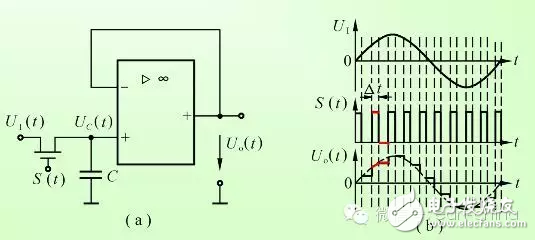
(2) Quantization and coding
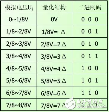
The number represented by 1 LSB of the least significant bit of the digital signal is the minimum number of units, called the quantized unit, expressed as Δ.
The sampled output voltage is expressed as an integer multiple of the minimum unit. This process is called quantization.
The process of expressing the quantized results in code is called encoding. The result of the encoded output is the output of the A/D converter.
A/D conversion circuit mode
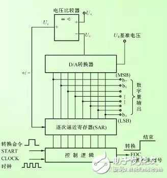
The analog-to-digital converter is roughly classified into parallel and parallel/serial A/D, successive approximation, double integral and count comparison A/D according to its working principle.
The successive approximation A/D consists of a voltage comparator, a D/A converter, a successive approximation register (SAR), and control logic.
ADC0808/0809
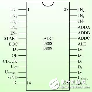
IN0~IN7: analog input pin;
ADDA, ADDB, ADDC: Channel address input.
CLOCK: Clock input.
ALE: Address latch enable.
START: Start the pulse input.
EOC: Conversion end signal terminal.
OE: Allow output.
D7~D0 pin: The 8-bit data obtained by conversion is output on these 8 pins, D7 is the highest bit, and D0 is the lowest bit.
UCC: Positive input of power supply, connected to +5 V.
GND: Ground terminal, the negative pole of the power supply is connected to this terminal.
UREF(+) and UREF(-): the high-level and low-level terminals of the reference voltage UREF, respectively.
The main technical parameters of the ADC
(1) Resolution
The resolution of the A/D is the magnitude of the input analog voltage change corresponding to the lowest bit change of the A/D output digital quantity. The resolution is also expressed by the number of bits of the output binary number. For example, the resolution of 8-bit A/D is 8. The more bits, the smaller the error and the higher the conversion accuracy.
(2) Quantization error
The process of approximating the analog quantity with a digital quantity is called quantization. The A/D conversion is generally carried out according to the rounding principle, and the resulting error is called quantization error, and the quantization error is less than or equal to 1 LSB.
(3) Accuracy
Accuracy is divided into absolute accuracy and relative accuracy.
In an A/D, the difference between the actual analog voltage corresponding to any digital and its ideal voltage is not a constant, the maximum value of the difference is defined as the absolute accuracy of the A/D; and the relative accuracy is defined as this The maximum difference is a percentage of the full-scale analog voltage, or a binary fraction is used to represent the corresponding digital quantity.
(4) Conversion time
The conversion time is the time required to complete an A/D conversion, which is the total time from the start of the A/D converter to the acquisition of the corresponding data.
ADC key performance indicators and misunderstandings
Because the ADC products are much smaller than the network products and servers, users and integrators have some misunderstandings about the key indicators when selecting products. In addition, some mainstream manufacturers deliberately guide, and the bidding specifications often have many non-key indicators. Must match the item. Let's take a look at these misunderstandings and the real key indicators.
Myth 1: The number of CPUs and the frequency. At present, most manufacturers adopt a similar general-purpose CPU architecture, but it is still possible to use CPUs from different manufacturers. Even the same manufacturer may be a different series. The most important thing is that the number of CPUs and the main frequency do not represent performance, unless they are the same software from the same manufacturer. Similarly, the exact same hardware configuration, the performance of different vendors' architectures and systems may differ by a factor of several, just as the contributions of the same few people in different management environments will vary greatly. Parallel computing is not well handled. Due to CPU overhead and lock issues, an increase in the number of CPUs does not mean an increase in performance. If one CPU can run out of the performance of 8 CPUs of other products, who will choose 8 CPU products? Cost, power consumption, and volume will be much larger. Therefore, CPU hardware configuration does not represent performance.
Myth 2: Memory. It is also related to the system architecture. Also related to the architecture, for the CPU exclusive memory architecture, even if only 2G memory is configured for each core, an 8-core product requires 16G memory, but each core can access only 2G of memory resources. Such a structure needs to be copied multiple times and saved multiple copies, which is inefficient and will eventually affect performance. For products with shared memory architecture, each core can access all memory resources, and only one copy of the data needs to be saved. In the case of a 32-bit operating system, the actual efficiency of the shared memory architecture 4G memory exceeds the arbitrary configuration of the exclusive memory architecture (currently, products other than the A10 are 32-bit operating systems, exclusive memory architecture). The 64-bit operating system breaks the 4G limit and the actual efficiency will be higher. Therefore, memory does not represent performance. If you must compare, you need to compare the memory resources accessible to each core.
Myth 3: Number of ports. ADC products are different from Layer 2/3 switches, and the number of ports means more devices can be connected. The ADC product deployment environment must have Layer 2/3 switches, and the server does not need to be directly connected to the ADC product. As long as the number of ports is greater than the actual required throughput and there are enough ports to connect to the switch.
Myth 4: Exchange ability. This indicator is also an indicator that follows the switch. Switch performance is closely related to the switching matrix chip switching capability, and the relationship with the CPU is not very large. The ADC products are different. The switch matrix is ​​not a necessary component. Most products use the general-purpose CPU architecture to use the PCIe bus expansion interface. This part is not the bottleneck of the ADC product. ADC performance basically depends on the efficiency of the CPU under the overall architecture of the system. And most of the products themselves are already the hardware architecture of the server, and there should be no indicators of the server's ability to exchange.
It can be seen that the misunderstandings are some indicators that use servers or switches. These hardware configurations do not represent the true performance of ADC products, but some vendors deliberately use these indicators (especially CPU and memory) to mislead customers to shield competitors. . The true key performance indicators of the ADC are as follows.
1. 4/7 layer throughput. Due to the CPU's complex 4-7 processing, the 4/7 layer throughput is much lower than the 2/3 layer throughput, but this is the data throughput that the ADC can really handle. This is why 2/3 layer throughput is not critical for ADC products. This indicator is usually tested by sending as many HTTP GET requests as possible. The server responds to large HTTP objects (such as 512Kbytes or 1MBytes, which are divided into several packets) and calculates the amount of data transmitted on the line without failure. The difference is that different meter manufacturers or different tests may not calculate the 2/3 layer header or GET request part, because the proportion of this part is very small, the impact is not great. Strictly speaking, horizontal comparison should determine the size of the HTTP object taken and whether to calculate the 2/3 layer header.
2. Layer 4 new connection rate per second (L4 CPS). Measure how many TCP new connections the ADC product can process per second. Usually the test method is to send as many HTTP GET requests as possible, and the server responds to smaller HTTP objects (such as 1Bytes, 128Bytes, 1KBytes). The ADC product only performs complex equalization based on 4 layers of information in the middle. Each connection requires a full 3-way handshake setup process, GET request, and TCP to close the connection process. This indicator is very important for ADC products to cope with a large number of bursts of connections. It is like the passing rate of a subway entrance. If the entrance is too small and the passenger flow suddenly increases, if the customer is unable to enter, the business will naturally be affected. When comparing the indicators, you need to pay attention to the size of the HTTP object taken.
3. 7 layers new connection rate per second (L7 CPS). Similar to the 4-layer new connection rate, only the ADC product needs to select the server according to the application layer information (usually test using url exchange), and only one HTTP request can be transmitted on each TCP connection. Using 7-layer processing requires higher CPU efficiency. Just as you need to check the guest for more information and security check when entering the subway, the pass rate will be reduced to a different extent than the normal pass rate. A10 products can usually achieve 70-80% of the 4-layer new connection rate, while many other manufacturers can only achieve 30-40%. When comparing the indicators, you should also pay attention to the HTTP object size and the number of requests transmitted per TCP connection.
4. 7 layers per second transaction rate (L7 RPS). Some vendors use L7 RPS as L7 CPS to confuse customers. The RPS test defines how many HTTP requests can be transmitted per TCP connection. There are usually 10 request/TCP connections and unlimited request connections/TCP connections for several test data. The L7 RPS value using 1 request is the L7 CPS. The difference is that in the L7 RPS test when each connection transmits multiple requests, the ADC can eliminate a lot of TCP connection setup and shutdown procedures. When comparing the indicators, you should also pay attention to the HTTP object size and the number of requests transmitted per TCP connection.
5. The number of concurrent sessions. If the new connection rate represents a subway entrance pass rate, the concurrent session represents the total number of people on the subway line. If the internal carrying capacity is not high enough, it will cause the passengers to squeeze the overload and finally smash. Concurrent session testing is not a simple way to save these entries in memory. In actual testing, you must periodically transmit data on each connection to verify that the device can accurately find existing sessions and forward data. The test may also subdivide the number of concurrent sessions in Layer 4 and the number of concurrent sessions in Layer 7. The difference is that the ADC establishes a session based on different information and the session entries occupied by each connection are different. Due to the large relationship between concurrent sessions and memory, ADCs in 32-bit systems cannot be made very large due to 4G memory limitations, and ADCs in 64-bit systems are not subject to this limitation.
6. Anti-DDoS attack capability (syn/sec). The concurrent session capability and new connection rate of ADC products are far greater than firewall products, so deploying a firewall outside the ADC can become a bottleneck. This requires the ADC itself to have sufficient robust anti-attack capabilities. Most ADC products currently use the Syn-cookie method to defend against DDoS attacks. The actual performance depends on the respective system architecture and processing algorithms.
It is worth mentioning that the F7's 7-layer new rate is significantly lower than the 4-layer new rate, so some data different from other vendors will be used as the L7 CPS response. F5 provides 3 L7 CPS/RPS indicators.
L7 ConnecTIon per Sec (1-1), client side connection 1 request / connecTIon, server side connection 1 request / connecTIon. General L7 CPS definition.
L7 Requests per Sec (1-inf), client side connection 1 request / connecTIon, server side connection unlimited request / connection. L7 CPS data that users usually see.
L7 Requests per Sec (inf-inf), the client side connects to unlimited request/connection, and the server side connects to unlimited request/connection.
The test report published by F5 clearly states that all of its Layer 7 tests enable connection multiplexing, so the test report sees "L7 Requests per Sec (1-inf)". When comparing L7 CPS, you should pay attention to using its CPS (1-1) indicator.
Other SSL metrics, DNS QPS metrics, and HTTP compression metrics are important for users who use such applications, but are not part of the generic key metrics and are not explained one by one.
Analysis and comparison of various ADCs
Description of Expandable Braided Sleeving For Cable Harness
1. Flame-retardant and halogen-free.
2.Can be cut with a common scissors without obvisous fray.
3.Softer and easier to be use on the outdoor fielad .
4. It offers durable abrasion resistance in a wide range of industrial applications.
5. The open weave construction allows an easy installation on a bundle of hoses
and cables, even if some with bulky or large connectors.
6. Totally expanded the sleeving can reach at least one point five times than the initial dimension.
7. Suitable for constructing and protecting cable harnesses or tidying cable looms.
8. Sleeve expands to allow the cables to pass through and then automatically shrinks back.
Application of Clean Cut Expandable Braided Sleeving For Cable Harness
1. Automobile wires protection
2. Structured cabling system
3.A/V cables & HDMI cables
4.Industrial hoses & tubes protection
Durability For Cable Sleeve,Specal Cable Sleeve,Grey Braided Cable Sleeve ,Wire Harness Protection Tube
Shenzhen Huiyunhai Tech.Co.,Ltd , https://www.hyhbraidedsleeve.com