Abstract: This paper introduces an embedded operating system Petalinux specially developed for MicroBlaze soft core processor, which successfully implements its migration on ML507 development board, and implements TCP/IP-based network on this system through LabVIEW software. Data is sent and received. At the same time, the network data transmission performance of the embedded system was tested.

Embedded system refers to a dedicated computer system that is application-centric, based on computer technology, software and hardware can be cut, can adapt to the application system, and has strict requirements on function, reliability, cost, size and power consumption. Mainly composed of embedded microprocessor, peripheral hardware devices, embedded operating system and user application software [1]. Petalinux is an embedded Linux developed by PetaLogix specifically for running on the MicroBlaze soft core processor of Xilinx FPGAs. The released version of Petalinux includes custom Linux 2.4/2.6 kernel source code, Uboot kernel code, related development tools, and development board reference hardware platform configuration, which greatly facilitates the use of developers and shortens the product development cycle.
Aiming at the problem of how to realize remote data transmission on embedded system, this paper presents a design and implementation scheme of embedded network data transmission system based on Xilinx ML507 development board. The client was written by LabVIEW programming software, and the real-time network data transmission between the development board and the PC was successfully realized. At the same time, the network data transmission performance of the Petalinux operating system was tested.
1 System platform construction1.1 Development board selection and hardware platform design
This design uses Xilinx EDK 10.1 to build a simplified hardware platform on the ML507 development board. The platform structure is shown in Figure 1.
The components are built in the form of IP cores inside the FPGA and are connected to each other through the SPLB bus and the XCL (Xilinx Cache Link) bus. The system has a 32-bit MicroBlaze soft core processor as the control center, the CF card is used to store the file system and the application configuration file; the interrupt controller is used to implement the interrupt control; the serial port module can output the system operation information during debugging; The Ethernet media access controller is used to implement the Ethernet function; the double rate synchronous dynamic random access memory is connected to the MicroBlaze processor through the XCL bus for accessing the off-chip memory [2].
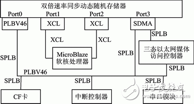
Figure 1 Hardware platform structure block diagram
1.2 Configuration of the software platform Before porting Petalinux, you must configure the BSP (Board Support Package). The so-called BSP, which is the code that provides specific operating system support for a given board, is a layer between the motherboard hardware and the operating system and should be said to be part of the operating system. The main purpose is to support the operating system so that it can run better on the hardware motherboard.
The Xilinx EDK already includes the corresponding BSP generator, so follow these steps to configure the software platform:
1 Copy the ~/hardware/edk_user_repository/PetaLogix/bsp/petalinux_v1_00_b folder in the unpacked Petalinux folder to the "~\\sw\\lib\\bsp" directory in the EDK folder.
2 Open the established hardware project and click the Software menu to launch Software Platform SetTIng. To configure the Software Platform window, click on Software Platform. In the OS&Library setTIngs sub-window, open the OS drop-down menu and select Petalinux. The version is only 1.00.b. If the first step is not completed, then after opening the OS drop-down menu, there will be no Petalinux option, and the rest of the options will remain the default.
3 Select the OS and Library configurable options, here mainly for the development board to configure the uclinux BSP, including Flash and Memory, and the configuration of the input / output debug port. Here, the main parameters are modified:
Lmb memory: dlmb_crtlr
Main memory: DDR_SDRAM
Stdin: RS232_Uart
Stdout: RS232_Uart
Finally, click OK to exit. The configuration of the MicroBlaze software platform based on Petalinux is completed.
After the software platform is configured, it is necessary to generate BSPs and libraries for the MicroBlaze processor according to the corresponding configuration, which makes it possible to exchange information between Petalinux and the development board. Go to the EDK's Software menu and click Generate BSP and Libraries. The board will automatically generate the board support package and library. The autoconfig.in file [3] can then be generated in the ~/microblaze_0/ libsrc/ petalinux_v1_00_b folder.
1.3 After the configuration of the transplant software platform of Petalinux operating system is completed, the kernel needs to be cut. The embedded system development generally adopts the cross-compilation method, and the kernel and the application program are compiled by the virtual machine on the PC. The specific steps are as follows [4]:
1 Copy the project folder to the Petalinux system directory;
2 Set the Petalinux environment variable;
3 Create a new user platform in the kernel;
4 build a kernel Makefile;
5 configure and compile the kernel;
6 xmd download image file to start the system.
The difference of the underlying hardware platform is determined by the difference of the system kernel configuration. The reference [2] gives a more detailed migration process for different situations in the ML402 development board, which can be used as a reference and will not be described here.
Use the debugging tool xmd provided by EDK to download the image file. After starting Petalinux, you can see the system startup process through the serial port HyperTerminal.
2 TCP / IP server-side program creationAfter the successful porting of Petalinux, the required server program was developed. In the virtual machine terminal, enter the petalinuxdist folder directory and enter the command petalinuxnewapp speedtest. Among them, speedtest is the server-side program name. After the creation is successful, a new folder named after the program speedtest is created in the ~/petalinux/software/userapps folder, which includes the .C application, the Makefile compilation rules, and the readme help file. Next, enter the speedtest folder directory, enter the command gedit speedtest.c, open the text editor, and edit the .C application.
The TCP/IP protocol is currently the most common network protocol, so the program also uses this protocol to achieve network interconnection. In Linux systems, network programming is provided by providing a Socket interface. The Socket interface is an API for TCP/IP networks that defines a number of functions or routines that programmers can use to develop applications on a TCP/IP network. The Socket data transmission of the network is a special type of I/O, and Socket is also a file descriptor. Socket has a function called Socket() similar to the open file. This function returns an integer Socket descriptor. Subsequent connection establishment, data transfer and other operations are implemented through the Socket.
There are two commonly used Socket types: Streaming Socket (SOCK_STREAM) and Datagram Socket (SOCK_DGRAM). Streaming Socket is a connection-oriented Socket for connection-oriented, error-free, consistent sequence, unlimited packet length and non-repeating TCP service applications; datagram Socket is a connectionless Socket The network is mainly transmitted by independent datagrams. The maximum length of datagrams is 32 KB. The transmission does not guarantee the order, reliability and non-repetition. It is usually used for single message transmission or where reliability is not important. According to the above characteristics, this application selects a streaming Socket.
The network server designed in this paper is mainly used to receive the instructions transmitted by the client, and then send the array to the client. The specific process is shown in Figure 2.
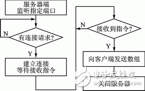
Figure 2 server-side communication process
The main code of the server-side speedtest.c is as follows [5]:
If((sockfd=socket(AF_INET,SOCK_STREAM,0))==-1){ //Create a socket Socket function can call the Socket function, which returns a // handle similar to the file descriptor
Fprintf(stderr,"socket error!\");
Exit(1);
}
If(bind(sockfd,(struct sockaddr *)&my_addr,sizeof(struct sockaddr))==-1){ //Bind function associates Socket with an end port on the machine, and listens for service request on this port.
Fprintf(stderr,"bind error!\");
Exit(1);
}
If(listen(sockfd,10)==-1){// The listen function converts a socket to a passive listening socket
Fprintf(stderr,"listen error!\");
Exit(1);
}
If((connfd=accept(sockfd,(struct sockaddr *)&their_addr,&sin_size))==-1){//Accept function receives a client connection request from the completion connection queue of the listening socket
Fprintf(stderr,"accept error!\");
Exit(1);
}
Printf("server:got connecTIon from %s\",inet_ntoa(their_addr.sin_addr));
Printf ("successfully connect.\\"); / / shows the connection is successful, start receiving client requests
If ((recfd=recv(connfd,buffer,recbufsize,0))==-1){// The recv function is used to control the read operation on the socket;
Recfd=recv(connfd,buffer,recbufsize,0);
}
Printf("\received string %d\");
For (i=1;i<=N;i++) a[i]=i;
b=sizeof(a);
If(send(connfd,a,b,0)==-1){//Controls the write operation to the socket, sending an array of 1 to 4 999
Fprintf(stderr,"send error!\");
Exit(1);
Printf("%d",b);
}
While(1){//convenient to test network transmission speed
Send(connfd,a,b,0);
}
Printf ("send successfully\\");
Close(sockfd); //Close a socket descriptor
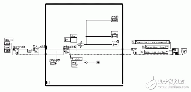
Figure 3 TCP/IP client LabVIEW simulation diagram
Start the server and recompile after the program is written, generate the image.bin file, and download the file.
Open the HyperTerminal and see the system startup, enter the username and password, enter the Petalinux system and execute the following commands:
Ls /bin
Speedtest
You can see the server-side startup statement output:
SOCKET: CreaTIng socket..done.
SOCKET: start bind socket..done.
SOCKET: start listen..done.
Indicates that the server is already listening and waiting for the client's connection request.
After the server is written, the PC client is written by LabVIEW programming software. The simulation diagram is shown in Figure 3.
Set the server IP address: 192.168.0.10, port: 8000. Click the Run button, you can see that when the PC client sends a connection request to the server on the development board, the server side outputs through the serial port:
SOCKET: start accept..server:got connection from 192.168.0.1
Successfully connect
Then the server sends 0~4 999 arrays to the PC client, and develops a visual graphical interface on the PC through LabVIEW software to view the data transmission content and the packet loss during data transmission. The interface is shown in Figure 4.
In Figure 4, the output data is converted into a waveform diagram and displayed as a rising line with no jump points in the middle, indicating that the data is not lost. Similarly, you can also see the value of each output through the data frame on the right. The observation also shows that the data is sent completely.
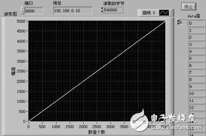
Figure 4 Client output interface after the server and client are connected
In order to test the data transmission speed of the system, the server-side program can continuously send the array by adding a loop statement, and test the network transmission speed of the system through the Dot Netpersec network speed test software. The interface is as shown in FIG. 5.
It can be seen that when using the Petalinux operating system, the network transmission rate of the system is 20.9 Mb/s on average. At this point, the client and server network data transmission was completed, and the transmission speed of Petalinux was tested. The results show that the Petalinux operating system can meet the general data transmission needs, and the subsequent access to peripheral devices can further develop and improve the system. .
Conclusion This paper briefly introduces the development and porting process of Petalinux system, as well as the creation process of TCP/IP client and server communication program, realizes real-time data transmission between PC and Petalinux operating system, and tests the transmission performance of the system. The experiment proves that Petalinux has good stability and real-time performance, which lays a foundation for network application development on the system.
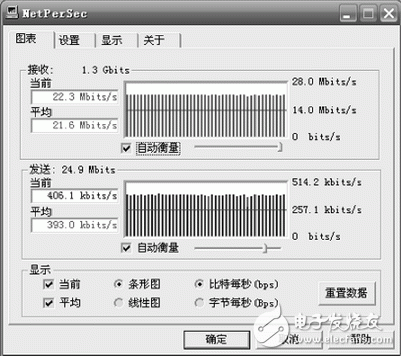
Figure 5 PetaLinux operating system network data transmission speed
references
[1] Huaqing Vision Embedded Training Center. Introduction to Embedded Linux C Programming [M]. Beijing: People's Posts and Telecommunications Press, 2009.
[2] Xue Huimin, Wu Chuanhua, Lu Houbing, et al. Transplantation of Petalinux operating system of MicroBlaze processor [J]. Microcontroller and Embedded System Application, 2011 (4): 6769.
[3] Xue Xiaogang, Ge Yimin. Xilinx ISE9.x FPGA/CPLD Design Guide [M]. Beijing: People's Posts and Telecommunications Press, 2007.
[4] John Williams.2010 Xilinx Professor Workshop—Embedded Linux on Xilinx MicroBlaze, 2010.
[5] Li Jun. Detailed explanation of embedded Linux device driver development [M]. Beijing: People's Posts and Telecommunications Press, 2008.
Yang Xie (Master's degree) and Lu Houbing (Lecturer), the main research direction is embedded system development; Wu Chuanhua (Professor), Qian Yi (Lecturer), the main research direction is software radio technology application.
LED Panel lights driver
LED Panel lights, as one energy saving lights in the Daily life, has became more and more popular in the world. We've designed led driver for this type led lights: 12W,18W,21W,24W,36W,48W,72W,85W,95W ect.According to different application, different country's household voltage, and different environment using, we designed suitable dirvers for these different situation.
Our led panel lights driver was made out of different case: aluminum, Iron, plastic ect. With input&output terminals, easy to install, especially for Class P certifed series, esay to combine with your already certified lamps, and then saving a lot cost!
Parameter:
Input voltage: 100-277vac / 100-240vac / 100-130vac / 180-240vac / 100-347V
output voltage: 25-40vdc / 27-42vdc / 35-45vdc / 50-70vdc / 12Vdc / 24vdc
current: 100mA-8000mA.
Power factor: >0.9
Dimming:0-10V / PWM / RX / DALI / Traic.
>=50000hours, 3-5 years warranty.
certificate: UL CE FCC TUV SAA ect.

FAQ:
Question 1:Are you a factory or a trading company?
Answer: We are a factory.Question 2: Payment term?
Answer: 30% TT deposit + 70% TT before shipment,50% TT deposit + 50% LC balance, Flexible payment
can be negotiated.
Question 3: What's the main business of Fahold?
Answer: Fahold focused on LED controllers and dimmers from 2010. We have 28 engineers who dedicated themselves to researching and developing LED controlling and dimming system.
Question 4: What Fahold will do if we have problems after receiving your products?
Answer: Our products have been strictly inspected before shipping. Once you receive the products you are not satisfied, please feel free to contact us in time, we will do our best to solve any of your problems with our good after-sale service.
Driver For Led Lights,Round Panel Lights Driver,Led Transformer
ShenZhen Fahold Electronic Limited , https://www.fahold.net