 Introduction: This article proposes a solution for the situation where the time of the calibrated electronic clock appears to be faster or slower when the electronic clock is used to make an electronic clock or a control system that is controlled according to the clock.
 In the application of single-chip microcomputers, this kind of situation is often encountered. When using an MCU to make an electronic clock or a control system that requires clock-based control, it will suddenly find that the time of the originally calibrated electronic clock has become faster or slower. So, try to adjust its travel time accuracy in various ways, but the final effect is still unsatisfactory, so I have to manually adjust it once in a while. So, can you make the clock more accurate? Now explore the following:
First, the analysis of the cause of error
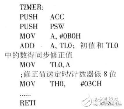
1. The timing pulse reference of the electronic clock of the single chip microcomputer is provided by the frequency of the external crystal oscillator after being divided by 12, and the timing is realized by the internal timing and counter. Therefore, the accuracy of the external crystal frequency directly affects the accuracy of the electronic clock timing. 2. The electronic clock of the single-chip microcomputer uses the internal timing, the counter overflow generates an interrupt (the 12MHz crystal oscillator is generally 50ms) and multiplies the corresponding multiplier to realize the conversion of the second, minute and time. As we all know, from timing, the counter generates an interrupt request to the response interrupt, which takes 3_8 machine cycles. The data stack and reload timing in the timer interrupt subroutine, the initial value of the counter also takes several machine cycles. Also. It takes a certain machine cycle to shift from the interrupted population to the interrupt subroutine. E.g:

As can be seen from the above procedure, the loading of the lower 8 bits from the interrupted population to the initial value of the timer/counter requires 2+2+2=6 machine cycles. Therefore, these 6 machine cycles are generally added to the initial value of the timer/counter during programming. However, from timing, it takes several machine cycles (3~8 machine cycles) for the counter to overflow the interrupt request to execute the interrupt. It is difficult to determine the exact value, which is why the electronic clock timing is not accurate.

Second, the solution
1, using high-precision crystal vibration scheme
Although the use of a high-precision crystal oscillator can slightly improve the accuracy of the electronic clock timing, the crystal oscillator is not the main factor that causes the timing of the electronic clock to be inaccurate, and the high-precision crystal oscillator is expensive, so it is not necessary to adopt this scheme. 2. Dynamic synchronization correction scheme
From the programmer's hand, the dynamic synchronization correction method is used to give timing, and the counter is given an initial value. The dynamic synchronization correction method is as follows: due to timing, after the counter overflows, it will automatically increment from O, so before the timer/counter is assigned again, the timing, the value in the counter low (TLO) and the initial value are added. Then send the timing, the counter, at this time, the value in the counter is the accurate value after the dynamic synchronization correction. The specific procedures are as follows:
With this method, it is believed that the accuracy of the electronic clock produced has been improved.
 
3. Automatic adjustment plan
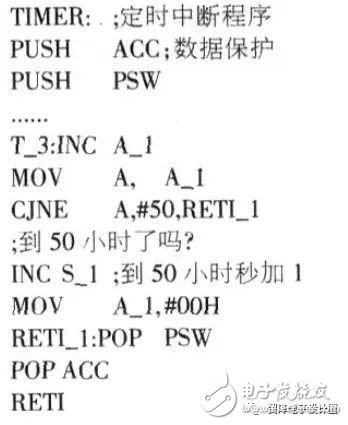
After using the synchronous correction scheme, the accuracy of the electronic clock is improved a lot, but due to the deviation of the crystal frequency and some other unknown factors (the same circuit board, the same program changed after a single-chip microcomputer, the travel time error is not the same, I do not know What is the reason? There will still be accumulation errors over time. To this end, an automatic adjustment scheme can be employed. It is actually a fault tolerant technology. The principle of automatic adjustment is: the time required for the error Is is actually measured, and then the second is adjusted by "1" or minus "1" after such a period of time. For example, the electronic clock is 1 second slower every 50 hours, and its automatic adjustment procedure is as follows:
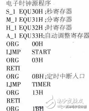
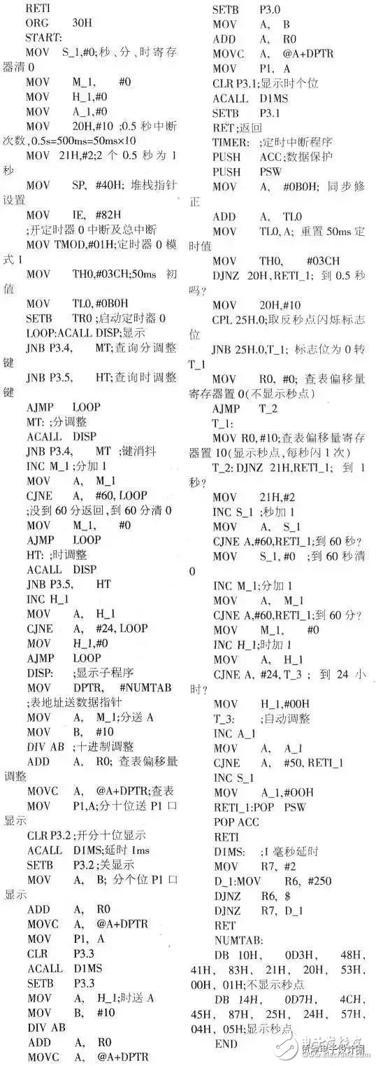
The following is a complete example:
Conclusion
Using this method is more time consuming, but the effect is very good. After the experiment, the monthly error can be controlled to about Is. If the number of days required for the error Is is measured again according to this method and the second adjustment is performed, the accuracy will be higher.
|
*These Xbox Series X battery is rechargeable battery pack, specially designed for your Xbox series X/S controller, 2 pieces of 800mAh Ni-MH battery and 1 piece of USB-C charging cable,no need any charging dock can save room and there is no need to worry about the storage of AA batteries.
* The X/S controller is protected from overcharge and power surge, ensuring the safety of charging at night.
* Can play when charging, no need to worry the controller power off, bring you great experience during games Rechargeable battery pack for Xbox Series X S controller, Fully charged is around 3-4 hours and provides up to 12 hours of playtime.it comes with the type-C cable, no extra adapter required. A GREEN light means charging, RED light means fully charged.
|
|
|
Product Name
|
Rechargeable Battery for Xbox Series X
|
|
weight
|
130g
|
|
Input
|
TYPE-C 5V
|
|
Output
|
DC2.4-3.0V
|
|
Product color
|
Black
|
|
Charging time
|
about 2 hours
|
|
play time
|
about 10 hours
|
|
OEM/ODM
|
warmly welcome
|
|
Advatage
|
100 QC test before shipping
|


Xbox Series X Battery,Rechargeable Xbox Series X Charge Kit,Xbox Series X Rechargeable Battery Pack,Xbox Series X Battery Pack
Shenzhen GEME electronics Co,.Ltd , https://www.gemesz.com