The function of the cty-100 current transformer is to convert a large primary current through a certain ratio to a secondary current with a small value. The cty-100 current transformer is used for protection, measurement and other purposes. For a current transformer with a ratio of 400/5, the actual current of 400a can be converted into a current of 5a. The transformer research report shows that the current transformer is installed in the switchgear for the purpose of instrumentation and relay protection such as ammeters. The current transformer wiring diagram is as follows:

It is impossible for each meter to be connected to a wire or bus with a large actual value, so it is converted into a secondary value with a small value by a cty-100 current transformer, and the actual value is reflected once by the ratio. The working principle and equivalent circuit of the cty-130 current transformer are the same as those of the general transformer, except that the primary winding is connected in series in the circuit under test, and the number of turns is small; the secondary winding is connected with a low impedance load such as an ammeter and a relay current coil. Short circuit. The primary current (ie, the current to be measured) and the secondary current depend on the load of the line under test, regardless of the secondary load of the current transformer.
When the cty-130 current transformer is running, the secondary side is not allowed to open. Because in this case, the primary current becomes the excitation current, which will cause the magnetic flux and the secondary voltage to greatly exceed the normal value and endanger the safety of people and equipment. Therefore, fuses are not allowed in the secondary circuit of the cty-130 current transformer, and devices such as ammeters and relays are not allowed to be removed without bypassing during operation.
The characteristics of the cty-130 current transformer are: (1) The primary coil is connected in series in the circuit, and the number of turns is very small. Therefore, the current in the primary coil is completely dependent on the load current of the circuit under test, and is independent of the secondary current; (2) The current coil of the instrument and relay connected to the secondary coil of the current transformer is very small, so under normal circumstances, the current transformer operates in a near short circuit condition.
The ratio of the primary and secondary rated current of the current transformer is called the rated mutual inductance ratio of the current transformer: kn=i1n/i2n Because the rated current i1n of the primary coil has been standardized, the rated current i2n of the secondary coil is unified to 5 (1 or 0.5). Ann, so the current transformer rated mutual inductance ratio has also been standardized. Kn can also be approximated as the turns ratio of the primary and secondary coils of the transformer, that is, kn≈kn=n1/n2 where n1 and n2 are the turns of the first and second coils.
Relay protection diagram caused by current transformer saturation
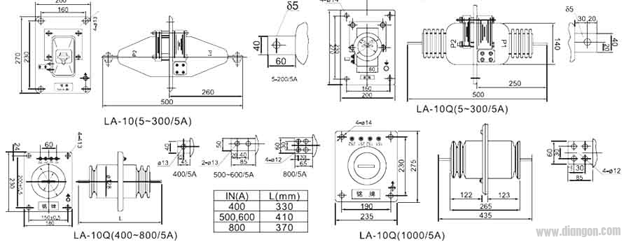
Lazb-10q current transformer
Principle test wiring diagram of voltage method for measuring current transformer ratio
SVLEC offers a comprehensive range of cable entry systems ethernet switch , D-sub connectors and programming ports for quick connections, easy separations and maintenance. Connecting the cabinet with the field is a key part of many installations.


Industrial Ethernet Switch,Interface Technology Product,D-sub connector,Cable entry system,Front panel interface
Kunshan SVL Electric Co.,Ltd , https://www.svlelectric.com