1 Introduction
It is very common for environmental information collection, but how to transmit the collected information is the key. The traditional system uses wired methods, which not only lays the line, but also is inconvenient and has poor portability. With the continuous development of wireless technology, the application of wireless in various fields is also increasing. It is the best solution to realize data collection and transmission through embedded systems through wireless systems, which not only simplifies the implementation, but also costs. relatively low.
This paper mainly uses C51 single-chip microcomputer as the control core to realize the environmental data acquisition system with wireless receiving and transmitting device.
2, system purpose
Design and manufacture a wireless environment monitoring and simulation device to detect peripheral temperature and illumination information. The device consists of one monitoring terminal and no more than 255 probe nodes (two actually produced). Both the monitoring terminal and the detecting node include a set of wireless transceiver circuits, which are required to have a wireless transmission data function, and share and receive one antenna.
The probe node has a number preset function, and the code preset range is 00000001B to 11111111B. The probe node is able to detect its ambient temperature and lighting information. The temperature measurement range is from 0 °C to 100 °C, and the absolute error is less than 2 °C; the illumination information only requires the presence or absence of measurement light. The probe node uses three 1.5V dry batteries in series and is powered by a single power supply.
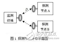
The monitoring terminal is powered by an external single power supply. The distribution of the probe nodes is shown in Figure 1. The monitoring terminal can directly communicate with each detecting node, and can display the detecting node number currently capable of communicating and the detected ambient temperature and illumination information.
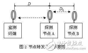
Each probe node adds information forwarding function, and the node forwarding function diagram is shown in FIG. 2. That is, the probe information of the probe node B can be automatically forwarded by the probe node A to increase the probe distance D+D1 between the monitoring terminal and the node B. The forwarding function should be automatically identified and completed, no manual setting is required, and the detection nodes A and B can be interchanged.
3. Scheme design and demonstration
3.1, program design
Solution 1: The use of at89s52 single-chip microcomputer, wireless transmission using LC oscillator, wireless reception using super heterodyne circuit, silicon light film, DS18B20, 8-bit DIP switch.
Solution 2: Adopt at89s52 single-chip microcomputer, wireless transmission adopts sound table device, wireless reception adopts super-regeneration circuit, silicon light film, DS18B20, 8-bit dial switch.
3.2. Scheme Argument:
(1) Wireless transmission circuit selection
Early transmitters used more LC oscillators, and the frequency drift was more serious. The emergence of a sound-sounding device solves this problem. Its frequency stability is roughly the same as that of a crystal oscillator, and its fundamental frequency can reach several hundred megahertz or even gigahertz. No need to multiply, the circuit is extremely simple compared to the crystal. The following circuit is a common transmitter circuit. Due to the use of the sound meter device, the circuit works very stable. Even if the antenna, the sound meter or other parts of the circuit are grasped, the transmission frequency will not drift. So obviously, the transmission uses a circuit that uses a sound meter device.
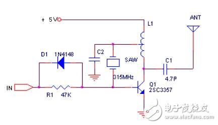
Figure 3 wireless transmitter
(1) Wireless receiving circuit selection
The receiver can use super regenerative circuit or superheterodyne circuit. The super regenerative circuit has low cost, low power consumption up to about 100uA, well-adjusted super-regenerative circuit sensitivity and one-level high-level, one-stage oscillation, one-stage mixing and two The superheterodyne receiver in the stage is similar. However, the super-regenerative circuit has poor operational stability and poor selectivity, thereby reducing the anti-interference ability. The figure below shows a typical super regenerative receiver circuit.
Although the advantages of super-difference are many, according to practical applications, most ordinary wireless transmissions use super-regeneration circuits, mainly because the cost of super-difference is relatively high, so the system finally uses super-regeneration circuits.

Figure 4 wireless receiving device
3.3. Summary of design scheme:
After analysis, I finally chose the second option. Although it is not the best solution, it has already met the requirements of the system in general. In terms of cost, the second solution is better.
SC Pigtail are available in simplex and Duplex Patch Cord, including single mode, multimode, OM3,9/125µm, 62.5/125µm, 50/125µm types. It's a great solution for fusion splicing,providing a fast way to make communication devices in FTTH field.In order to assure of high performance,SC pigtails are made with premium grade connectors. SC Pigtail Single Mode is normally a yellow jacket,while Pigtail SC is an orange or aqua jacket and SC Multimode OM3 Fiber Pigtail is normally Aqua in Color.Foclink,a reliable supplier of SC pigtail, is always beside u 7*24.
SC Pigtail
SC Pigtail,Pigtail SC,SC Pigtail Single Mode,SC Sm Pigtail
Foclink Co., Ltd , https://www.scfiberpigtail.com