1 Intelligent vehicle instrument system structure
This intelligent vehicle-mounted instrument has the functions of most traditional vehicle-mounted instruments. The driver can obtain the current vehicle status information through the display interface of the vehicle-mounted instrument, such as vehicle speed, oil pressure, oil temperature, water temperature, oil pressure, or battery power.
The traditional vehicle instrument is directly connected to the vehicle's sensor, and the instrument system obtains the current state of the car through the analog value of the sensor, and the accuracy is not high. The intelligent vehicle-mounted instrument designed in this paper is not simply connected to the sensor, but connects the entire vehicle into a network structure through the CAN controller. The vehicle components are equipped with a CAN controller, and the vehicle components are connected by twisted pairs to form a network system to realize the electronicization of the components. At the same time, the electronicization of on-board instruments and car parts has also improved the accuracy and reliability of the car and reduced the incidence of failures.
The vehicle-mounted intelligent instrument is mainly divided into hardware system based on S3C2440 processor and software system under WinCE environment. The hardware system provides the foundation for the entire control system and is responsible for CAN bus communication. The software system provides the CAN bus hardware driver and the instrument upper application program under WinCE.
2 Hardware design
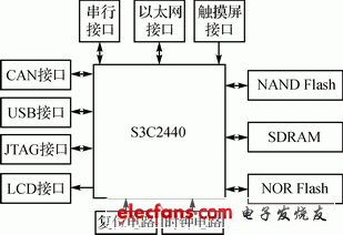
The hardware system uses S3C2440 as the core, RAM memory, NOR Flash and NAND Flash as storage media, and expands some peripheral devices to be responsible for the input and output of system information, such as CAN bus communication unit, LCD display, touch screen, universal serial port, USB device , Ethernet interface, etc. The system hardware structure is shown in Figure 1.

Figure 1 Block diagram of system hardware structure
Among many interfaces, the CAN bus communication unit is a key part in the vehicle communication process. In each important part of the car, the corresponding CAN control unit is configured, and each CAN bus control unit is connected by a twisted pair. Each component of the car sends out the current status information of the component from the CAN control unit, sends it to the CAN unit of the intelligent vehicle instrument through the twisted pair, and sends the data to the system through the CAN interface of the system. After the vehicle-mounted instrument system obtains the data, the current state information of the car parts is obtained through data processing.
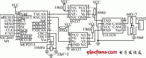
The CAN bus interface circuit is shown in Figure 2. Adopt Microchip's CAN bus controller MCP2515. MCP2515 fully supports CAN 2.0A / B technical specifications, speed up to 1 Mbps; SPI interface standard makes it easier to connect with S3C2440; can send and receive standards and extended data frames and remote Frame; comes with 2 acceptance mask registers and 6 acceptance filter registers, which can filter out unwanted messages and reduce the overhead of the microprocessor. The CAN bus transceiver uses TJA1050, which provides the interface between the CAN controller and the physical bus and the differential transmission and reception functions of the CAN bus.

Figure 2 CAN bus interface circuit
In order to enhance the anti-interference ability of the CAN bus node and improve the stability of the system, an optocoupler isolator 6N137 was added between the CAN controller and the CAN transceiver instead of directly connecting the TXCAN and RXCAN terminals to the transceiver The electrical isolation between CAN nodes on the bus. At the same time, this also solves the problem of level compatibility between MCP2515 and TJA1050, and can also suppress spikes and noise interference in the CAN network. The two power supplies used in the optocoupler circuit must be completely isolated, otherwise it will lose its meaning. The power supply can be isolated using a low-power power supply isolation module or multiple switching power supply modules with 5 V isolated output. Although these parts increase the complexity of the interface circuit, they improve the stability and security of the node.
At the CAN interface, two 60 Ω resistors (120 Ω total) on the CAN communication line play a role in increasing the load and reducing echo reflection, which is a remedy for impedance matching. Connect a capacitor between the two 60 Ω middle parts and the ground to prevent interference.
The AGM is a newer type sealed lead-acid that uses absorbed glass mats between the plates. It is sealed, maintenance-free and the plates are rigidly mounted to withstand extensive shock and vibration. Nearly all AGM batteries are recombinant, meaning they can recombine 99% of the oxygen and hydrogen. There is almost no water is loss.
The charging voltages are the same as for other lead-acid batteries. Even under severe overcharge conditions, hydrogen emission is below the 4% specified for aircraft and enclosed spaces. The low self-discharge of 1-3% per month allows long storage before recharging. The AGM costs twice that of the flooded version of the same capacity. Because of durability, German high performance cars use AGM batteries in favor of the flooded type.
Advantages
· Inexpensive and simple to manufacture.
· Mature, reliable and well-understood technology - when used correctly, lead-acid is durable and provides dependable service.
· The self-discharge is among the lowest of rechargeable battery systems.
· Capable of high discharge rates.
Long Life Vrla Batteries,Vrla Battery,High Capacity Battery,12V Electrical Battery
Starlight Power Industrial Company Limited , https://www.starlite-power.com