Abstract: The development of electric vehicles helps to alleviate energy shortages and environmental pollution problems. In view of the fact that lithium batteries are gradually being used in electric vehicles, this paper proposes a design scheme for an electric vehicle lithium battery management system based on OZ8940 chip. The system includes voltage, current, temperature acquisition circuit, equalization circuit, MCU main control circuit, I2C communication circuit, CAN communication circuit, display unit. The system design scheme is simple and reliable, realizing the real-time monitoring and protection of lithium batteries.
The use of electric vehicles helps to protect the environment and solve the energy shortage problem. As the energy source of electric vehicles, battery packs work normally and are an important guarantee for safe driving. Therefore, the management of the working status of battery packs is particularly important. In recent years, research on battery management systems has also received increasing attention. The function of the battery management system is to monitor the state of the battery pack in real time, implement the necessary management and protection measures to improve the utilization rate of the battery pack, ensure the safety and reliability of the battery pack work, and then ensure the driving safety.
1 Introduction to basic system functions
The designed lithium battery management system uses battery monitoring chips to monitor the voltage, current, temperature and other information of electric vehicle batteries in real time. After the collected voltage, current, temperature and other information are processed by the microprocessor, the corresponding information is displayed on the display screen. If the battery status information exceeds the normal range, the system automatically cuts off the charge and discharge circuit and alarms. The application of the balance circuit extends the service life of the battery pack. The system structure is shown in Figure 1.
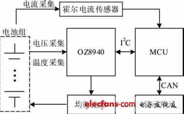
Figure 1 Basic structure of the battery management system
2 System hardware design
The system uses O2Micro's OZ8940 chip as the battery information acquisition chip. OZ8940 is a low-power chip, the current is less than 500μA during operation, and less than 50μA in sleep mode. It can support the information measurement of 6 ~ 12 cells in series, and the total voltage measurement range is 9 ~ 60 V. The internal includes 12 channels of 12 Bit voltage acquisition ADC, resolution 2.44 mV. 1-channel on-chip temperature acquisition ADC, accuracy is 12 bits, 2-channel off-chip temperature acquisition ADC, accuracy is 12 bits, resolution 1.22mV. OZ8940 can provide two-level protection function, the first Primary protection includes over-voltage, over-current, and over-temperature protection. The second level of protection is the protection of permanent external extremely high overvoltage faults. In addition, OZ8940 supports two equalization methods: internal balance and external balance. The application of equalization technology makes the characteristics of the battery pack maintain a good consistency during charging, which helps to extend the service life of the battery pack. OZ8940 communicates with MCU through I2C interface.
2.1 Single cell voltage monitoring
As shown in Figure 2, 12 cells are connected in series to form a battery pack, and the terminals are drawn from the positive and negative poles of each cell. The input voltage range of the cells is -0.5 V ~ 8 V. The terminals pass through the RC low pass After the circuit is introduced to the BAT port of OZ8940, as the input terminal of the battery voltage. The RC low-pass circuit can eliminate high-frequency interference in the signal. In OZ8940, these 12 voltage signals are respectively introduced into the internal 12-bit precision ADC through a multiplexer for conversion. The conversion result is sent to the internal logic and communicates with the MCU via the I2C interface.
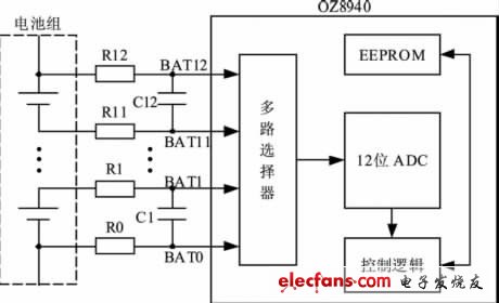
Figure 2 Voltage acquisition
2.2 Current monitoring
A Hall current sensor is used to collect the charging and discharging current of the battery pack, as shown in the current collecting part in FIG. 1. The collected information is sent to the MCU for processing.
Led Projecting Lamp,Six Modules Project Lamp,Mini Project Solar Garden Lamp,Outdoor Waterproof Project Lights
Jilin Province Wanhe light Co.,Ltd , https://www.wanhelight.com