Especially in wireless communication applications, it is often necessary to switch the output frequency of a PLL (Phase Locked Loop) synthesizer in a very short time. In such cases, it is often desirable to achieve a stable output frequency in less than 20 μs after a relatively large frequency jump. Below we describe how the ultra-low noise and ultra-low parasitic 0.37GHz to 6.39GHz integer N PLL synthesizer LTC6946 with integrated VCO can achieve this goal.
More specifically, for a 20MHz frequency step, we select the appropriate LTC6946 parameter to stabilize its output to within 10kHz of the final frequency in the shortest possible time. For this example, we can use a 20MHz comparison frequency (phase-frequency detector frequency, fPFD) for the LTC6946. For example, this means that if the reference input frequency (fREF) is 100MHz, the reference divider (R) must be set equal to 5.
The rule of thumb for implementing a stable loop in a PLL system is to make the loop bandwidth (LBW) at least 10 times smaller than the fPFD. Therefore, and in order to optimize fast stability, in this example we can set LBW = 2MHz. This is in contrast to setting LBW equal to the frequency offset, where the in-band phase noise of the PLL crosses the phase noise of the VCO to optimize overall phase noise performance.
We chose to generate a 4 GHz output signal from the LTC6946-3 and use the PLLWizardTM software tool to determine the filter component values ​​required to build the LTC6946 peripheral circuitry. PLLWizard is a free tool that is provided to aid in the design and simulation of the LTC6946.
After entering the desired fPFD and LBW values ​​in the PLLWizard GUI and clicking the mouse a few times, we have the loop filter component values ​​that we can install into the LTC6946 circuit. The screenshot in Figure 1 shows how the PLLWizard tool simplifies the design process of the LTC6946. To verify that our work is correct, we simulate the expected phase noise of the LTC6946 under the given conditions. Figure 1 includes the predictions for PLLWizard.
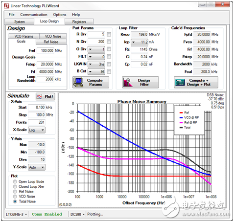
Figure 1: PLLWizard tool settings and prediction of LTC6946 phase noise at 4GHz, 20MHz fPFD and 2MHz LBW
Next, we power up the circuit and measure the phase noise with the Keysight E5052A source analyzer. Figure 2 shows that this measurement is very consistent with the above simulation results.
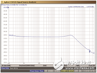
Figure 2: Output phase noise of the LTC6946 measured by the Keysight E5052A source analyzer
Now, let's check that the output of the LTC6946 settles to within 10 kHz of the final frequency value after a step frequency of 3.90 GHz to 4.00 GHz. The E5052A captures transient response as shown in Figure 3.
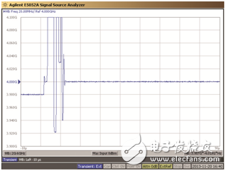
Figure 3: Stabilization process of the LTC6946 output after a 20MHz frequency transition
We zoomed in on the y-axis by reducing the bandwidth of the E5052A detector in the above measurements to more accurately determine the settling time. Figure 4 illustrates how the output of the LTC6946 settles to less than 10 kHz from the final frequency value in less than 15 μs.
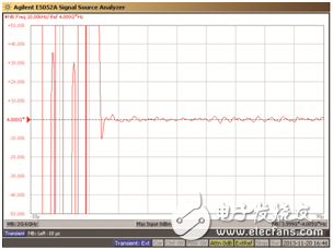
Figure 4: The output of the LTC6946 is stable in less than 15μs after a 20MHz frequency step
It should be mentioned that the new synthesizer IC with integrated VCO uses multiple internal VCO sub-bands to cover its entire output frequency range. Each time the output frequency of the synthesizer IC changes, the IC must run an internal VCO calibration routine to determine the correct VCO sub-band. In the case where the LBW of the PLL is relatively large, as in our example, when switching the frequency, the time required to finalize the calibration process will account for a large portion of the settling time. Since the LTC6946-3 is generally capable of running this calibration process in just over 10μs, we are able to achieve a total settling time of approximately 15μs.
Figures 3 and 4 show that the output frequency of the LTC6946 jumps and goes during VCO calibration. This behavior is shown here to illustrate the reason. In most practical situations, people don't want the output frequency to jump around like this. By setting the "MTCAL" register on the LTC6946 to "1" ("1" is the default), this can be handled by suppressing the RF output during calibration. It is recommended that "MTCAL" is always set to "1".
You can follow and modify the steps provided in this article to determine the application parameters that are right for you. The DC1705 (LTC6946 Demonstration Board) provides a comprehensive development platform for evaluating the performance of PLLs in a variety of filter and frequency configurations. The DC2026 Linduino® USB Controller Board provides a communication interface between the PLL demo board and a PC using the PLLWizard tool.
The PLLWizard GUI allows full control of the DC1705. However, in order to set the PLL IC for fast frequency switching in a very short time, we will write some Linduino code and run the DC2026 at the highest SPI interface speed of the DC2026. To quickly set up the PLL IC via the SPI interface, it is critical to use the DC2026 and custom code, and if needed, the Arduino IDE can be used to provide a code development environment.
We have evaluated the phase noise behavior of our fast stable synthesizers. However, considering that we have made the loop bandwidth relatively large, one might ask how the parasitic performance will be affected. One might expect that parasitic performance can be compromised under these conditions when using a typical synthesizer IC. This is not the case with the LTC6946. At 2MHz loop bandwidth and 20MHz fPFD, achieving near-90dBc of reference spurious noise (unwanted signal from 4GHz carrier offset fPFD = 20MHz) is compelling, as confirmed by the LTC6946 spectrum shown in Figure 5. That way.
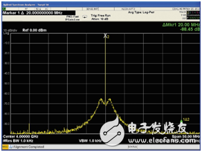
Figure 5: The output spectrum of the LTC6946 exhibits unusually low spurious noise at 4GHz output with a loop bandwidth of 2MHz
The LTC6946 is known for its ability to produce low phase noise and low parasitic output. We show in this article that with the LTC6946, ultra-fast frequency switching can be achieved without compromising parasitic performance. In frequency hopping communication applications, the LTC6946 is an excellent choice for low phase noise frequencies.
ZGAR Aurora 1200 Puffs
ZGAR electronic cigarette uses high-tech R&D, food grade disposable pod device and high-quality raw material. All package designs are Original IP. Our designer team is from Hong Kong. We have very high requirements for product quality, flavors taste and packaging design. The E-liquid is imported, materials are food grade, and assembly plant is medical-grade dust-free workshops.
Our products include disposable e-cigarettes, rechargeable e-cigarettes, rechargreable disposable vape pen, and various of flavors of cigarette cartridges. From 600puffs to 5000puffs, ZGAR bar Disposable offer high-tech R&D, E-cigarette improves battery capacity, We offer various of flavors and support customization. And printing designs can be customized. We have our own professional team and competitive quotations for any OEM or ODM works.
We supply OEM rechargeable disposable vape pen,OEM disposable electronic cigarette,ODM disposable vape pen,ODM disposable electronic cigarette,OEM/ODM vape pen e-cigarette,OEM/ODM atomizer device.

Aurora 1200 Puffs,Pod System Vape,Pos Systems Touch Screen,Empty Disposable Vape Pod System,1200Puffs Pod Vape System
ZGAR INTERNATIONAL TRADING CO., LTD. , https://www.oemvape-pen.com