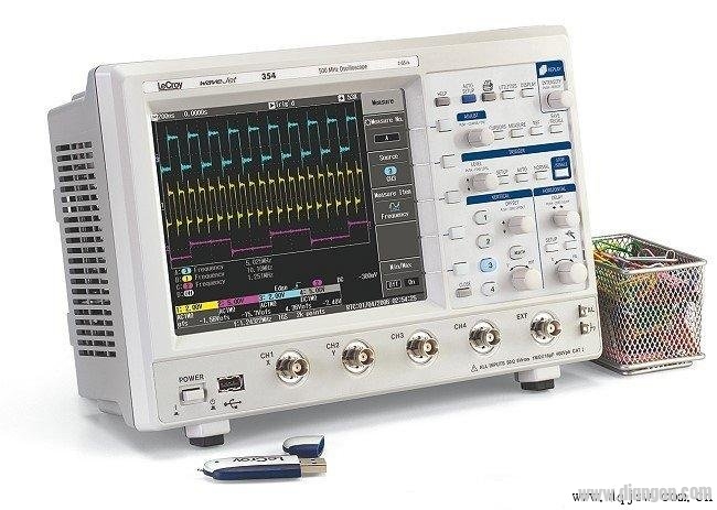
How do junior engineers correctly use an oscilloscope to measure ripple? An oscilloscope is a powerful tool that converts invisible electrical signals into visible waveforms, allowing engineers to observe and analyze various electrical phenomena over time. It’s essential for measuring voltage, current, phase differences, and more. This article explores the proper techniques for using an oscilloscope to accurately measure ripple, especially for those who are just starting out in electronics.

When using an oscilloscope, the primary measurement is always related to voltage. It can capture both DC and AC signals, as well as complex waveforms like pulses or non-sinusoidal signals. The device is also capable of analyzing different parts of a waveform, such as peaks, dips, and transitions—something no other instrument can match.
Junior engineers often face challenges when measuring ripple with an oscilloscope. Common mistakes include using long ground leads, placing the probe loop near power components, and allowing excessive inductance between the probe and the capacitor. These errors can introduce noise and distort the actual signal, making accurate measurements difficult.
To avoid these issues, it's important to follow best practices. First, set the bandwidth limit on the oscilloscope to filter out high-frequency noise that isn’t relevant to the ripple being measured. Second, remove the probe’s "cap" and create a short ground connection. This reduces the antenna effect of the long ground lead, minimizing electromagnetic interference.
In isolated power supplies, common-mode currents can cause voltage drops between the power ground and the oscilloscope ground, which may appear as ripple. To prevent this, ensure proper common-mode filtering in the power design. Wrapping the oscilloscope leads around a ferrite core can also help reduce common-mode current without affecting the differential measurement.
Power ripple performance can be further improved by considering the system-level design. Inductance from wiring and PCB traces, along with bypass capacitors, form low-pass filters that reduce ripple and high-frequency noise. For example, a one-inch conductor with 15 nH inductance and a 10 μF capacitor can create a filter with a cutoff frequency of around 400 kHz, effectively suppressing high-frequency noise while leaving the ripple unaffected.
The output voltage of a power supply should ideally be stable, but it’s usually derived from rectified and filtered AC. This process leaves behind some residual AC components, known as ripple. Larger ripples can interfere with sensitive components like CPUs and GPUs, so minimizing them is crucial. The smaller the ripple, the better the performance of the circuit.
Measuring ripple correctly requires attention to detail. By following the right techniques and avoiding common pitfalls, junior engineers can significantly improve their results. Remember to maintain the oscilloscope properly and ensure safe operation to protect both the equipment and the user. With practice and understanding, anyone can master the art of measuring ripple with an oscilloscope.
Panoramic Elevator,Full View Scenic Passenger Elevator,View Elevator,Outdoor Panoramic Glass Elevator
ZHONG HAN INTERNATIONAL TRADE CO., LTD , https://www.cck-ht.com