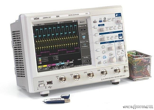
How do junior engineers correctly use an oscilloscope to measure ripple? Oscilloscopes are essential tools that convert invisible electrical signals into visible waveforms, allowing engineers to analyze the behavior of various signals over time. They are widely used for observing voltage, current, phase differences, and more. This article explains how a beginner can effectively measure ripple using an oscilloscope, ensuring accurate results and avoiding common mistakes.
All measurements made with an oscilloscope ultimately come down to voltage measurement. It can capture both DC and AC signals, as well as complex waveforms like pulses or non-sinusoidal signals. The oscilloscope is particularly useful in measuring specific parts of a pulse waveform, such as the peak or droop, something that other instruments cannot do as effectively.
Junior engineers often face challenges when measuring ripple, and they tend to make several common errors. These include using long ground leads on the probe, placing the loop formed by the probe near power components, and allowing excess inductance between the probe and the output capacitor. Such practices can introduce noise and distort the actual signal being measured.
When working with power supplies, high-speed signals and electromagnetic interference can easily be picked up by the oscilloscope, especially from transformers and switching components. This can lead to inaccurate readings if not properly managed.
To measure ripple correctly, it's important to apply bandwidth limits to reduce high-frequency noise that isn't relevant. Additionally, removing the probe cap and shortening the ground lead helps minimize antenna-like effects that can pick up unwanted signals. Wrapping the ground wire around a ferrite core can also help suppress common-mode currents, improving measurement accuracy.
In isolated power systems, common-mode currents can create voltage drops between the power ground and the oscilloscope ground, which may appear as ripple. To avoid this, proper filtering and grounding techniques must be applied. Winding the oscilloscope leads around a ferrite core can act as a common-mode inductor, reducing interference without affecting the differential measurement.
Power supply ripple performance can be further improved by integrating bypass capacitors and inductors into the system. These components form a low-pass filter that reduces both ripple and high-frequency noise. In some cases, a simple 15 nH inductor and 10 μF capacitor can create a cutoff frequency below the ripple frequency, significantly reducing noise levels.
The DC output of a power supply should ideally be stable, but it's often derived from rectified AC, which can leave behind residual AC components. These are referred to as ripple, and larger ripples can affect the performance of sensitive components like CPUs and GPUs. Therefore, minimizing ripple is crucial for reliable operation.
By following best practices, junior engineers can ensure accurate ripple measurements and avoid common pitfalls. Proper setup, grounding, and filtering are key to achieving reliable results. Always remember to handle the oscilloscope carefully and follow safety procedures to protect both the equipment and the user.
Panoramic Elevator,Full View Scenic Passenger Elevator,View Elevator,Outdoor Panoramic Glass Elevator
ZHONG HAN INTERNATIONAL TRADE CO., LTD , https://www.cck-ht.com