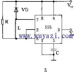
The figure shows a 555 circuit with a multi-vibrator composed of an external resistor R and an inductor L. The oscillation frequency is related to the values ​​of R and L. At the moment of power-on, since the current in the inductor L cannot be abrupt, Il=0, the output of the “1†and 3 pins of the 2 and 6 pins is 0, and the internal discharge tube of the circuit is turned on, and the voltage across the L is approximately equal to the power supply voltage. As Il increases, Vl gradually decreases, that is, the potential of 2 and 6 pins decreases, and when it drops to 1/3 Vcc, the output changes from low to high. At this time, the inner discharge tube of 555 is turned off, and Il is gradually decreased. 2. The potential of the 6-pin is continuously increased with the decrease of Il. When it rises to 2/3Vcc, the output changes from high to low. The oscillation frequency f is proportional to R and inversely proportional to L. In practical applications, R is generally adjusted to change the oscillation frequency.
China manufacture for Popular Custom Vape Pen, high quality battery, quality e-liquid and food safty material.
Prefilled Vape
Newmax Electronics Co.,Limited , https://www.advvape.com