Minimizing the switching ripple and transients of the switching regulator is important, especially when powering noise-sensitive devices such as high-resolution ADCs, the output ripple will behave as a unique spur on the ADC output spectrum. To avoid reducing signal-to-noise ratio (SNR) and spurious-free dynamic range (SFDR) performance, switching regulators are often replaced with low dropout regulators (LDOs), sacrificing the high efficiency of switching regulators for a cleaner LDO output. Understanding these artifacts allows designers to successfully integrate switching regulators into more high-performance, noise-sensitive applications.
This article describes an effective way to measure output ripple and switching transients in a switching regulator. The measurement of these parameters is very careful, because poor settings can cause reading errors, and loops formed by the oscilloscope probe signal and the ground lead can cause parasitic inductance. This increases the magnitude of the transients associated with fast switching transients, so short connections, efficient methods, and wide bandwidth performance must be maintained. Here, the ADP2114 dual 2 A/single 4 A synchronous step-down DC-DC converter is used to demonstrate the method of measuring output ripple and switching noise. This buck regulator is highly efficient with switching frequencies up to 2 MHz.
Output ripple and switching transients
Output ripple and switching transients depend on the regulator topology and the values ​​and characteristics of the external components. The output ripple is the residual AC output voltage and is closely related to the switching operation of the regulator. Its fundamental frequency is the same as the switching frequency of the regulator. Switching transients are high frequency oscillations that occur during switching transitions. Their amplitude is expressed in terms of the maximum peak-to-peak voltage, which is difficult to measure accurately because it is highly correlated with the test setup. Figure 1 shows an example of output ripple and switching transients.
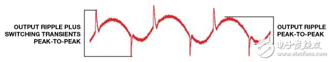
Figure 1. Output ripple and switching transients
Output ripple considerations
The regulator's inductance and output capacitance are the main components that affect the output ripple. A smaller inductor produces a faster transient response, but at the expense of a larger current ripple; a larger inductor will make the current ripple smaller, at the expense of a slower transient response. Capacitors with low effective series resistance (ESR) minimize output ripple. Ceramic capacitors with dielectric X5R or X7R are a good choice. Large capacitors are often used to reduce output ripple, but the size and number of output capacitors are derived from the cost and PCB area.
Frequency domain measurement
For power engineers, it is useful to consider the frequency domain when measuring unwanted output signals. It provides a better view of which discrete frequencies the output ripple and its harmonics are located, and which ones are different. Power level. Figure 2 shows an example of a spectrum. This type of information helps engineers determine if the selected switching regulator is suitable for their wideband RF or high speed converter applications.
For frequency domain measurements, connect a 50Ω coaxial cable probe across the output capacitor. The signal terminates at the 50Ω termination resistor at the input of the spectrum analyzer through a DC blocking capacitor. DC blocking capacitors prevent DC current from passing through the spectrum analyzer and avoid DC load effects. The 50Ω transmission environment minimizes high frequency reflections and standing waves.
The output capacitor is the primary source of output ripple, so the measurement points should be as close as possible. The loop from the signal tip to the ground point should be as small as possible to minimize the extra inductance that can affect the measurement. Figure 2 shows the output ripple and harmonics in the frequency domain. The ADP2114 produces a 4 mV pp output ripple at the fundamental frequency under specified operating conditions.
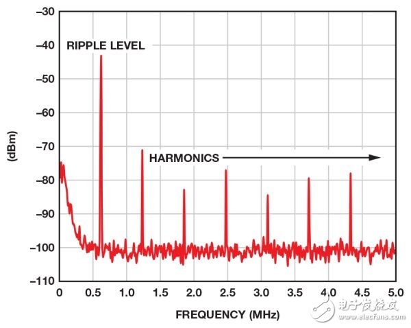
Figure 2. Frequency domain diagram using a spectrum analyzer
Time domain measurement
With oscilloscope probes, long ground leads are not used to avoid ground loops because the loop formed by the signal tip and long ground leads creates additional inductance and high switching transients.
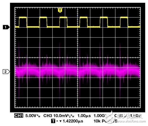
When measuring low-level output ripple, use 1&TImes; passive probe or 50Ω coaxial cable instead of 10&TImes; oscilloscope probe, because 10 & TImes; probe will attenuate the signal by 10 times, thus reducing the low level signal to Oscilloscope noise floor. Figure 3 shows the suboptimal detection method. Figure 4 shows the waveform measurements when using a 500MHz bandwidth setting. High-frequency noise and transients are measurement spurious signals caused by loops formed by long ground leads and are not inherent to switching regulators.
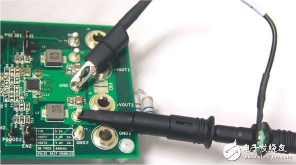
Figure 3. Ground loop produces output error
ZhenHuan`s line of Battery Charger range in output power from 4.2 Watt to 150 Watt features high energy efficiency Level VI and reliability, with quick charging function for 18650 batteries and li-ion batteries, etc. Our desktop versions ac to dc power charger adopts constant voltage and constant current mode, all available with 2 colors LED indicator for charging status(Green and Red light). ZhenHuan`s power charger adapters solutions also includes class I and class II installations, equipped with IEC320-C8, IEC320-C6 and IEC320-C14 three standard AC inlet options.

Battery Charger Phones,Battery Charger Motorcycle,Battery Charger 42V,Best Battery Charger,Golf Car Battery Charger,Cell Phone Battery Charger
Shenzhenshi Zhenhuan Electronic Co Ltd , https://www.szzhpower.com