This project requires the Raspberry Pi to drive eight AC outlets, which are connected to the Christmas tree lights. In order to make the light change dynamically, here is the programmable RGB LED light. I can use the Raspberry Pi to generate sounds to control the color of these LEDs, so this design uses a Raspberry Pi instead of an Arduino controller.
The first step: preparing materials
The materials explained first are used in my design and can be changed according to my own situation.
Controller section:
1, Raspberry Pi
·SD card
·USB WiFi network card
2, 5V SainSmart 8-channel SSR module board
· It is necessary to prevent the switch button sound of the mechanical relay from affecting the SSR. This module board has 2 times magnification for each SSR, which is enough to support all the Christmas tree lights.
3, jumper
4, JST SM plug and socket
5, 32 foot wire (or four 8 foot line)
6, 8 extension cords
7, 2 power supply terminal boards
8, power board
9, the power supply
· A 5V, 3A or larger power supply for driving LEDs and Pi
· A 5V, 1A or larger power supply for driving the SSR module
10, the outer shell
11, the speaker
LED light section:
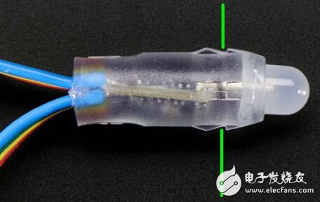
1, 12mm RGB LED lights (AdafruitWS2801 allows Pi to generate pulses to control the LED)
2, fixed LED plastic ABS sheet
3. Lexan sheets that reflect LED lights
4, black spray paint
5, white spray paint
6, wooden blocks
Christmas tree:
1. White 100 light strand x 4
2. White 50 light strand
3. Red 100 light strand x 2
4. Green 100 light strand x 2
5. Blue 100 light strands x 2
Step 2: Debug Raspberry Pi
Before wiring, the Pi needs to be tested to ensure that all components remain connected. The debugging process also needs to be done before assembling the enclosure and connecting the monitor and keyboard.
In addition, you need to install AdaFruit's Occidentalis operating system on the Pi, and then perform the following steps:
1) Configure PI boot command prompt (not GUI interface)
2) Set up the wireless network interface
3) Install Telnet and FTP server
4) Install Pygame
The above installation setup instructions can be searched online, and a large number of Raspberry Pi resources are available.
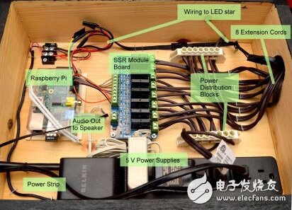
The third step: loading the case
There is no detailed introduction to how to build the shell, as it is just a wooden box. Drill 1.5" diameter at both ends of the housing. All extensions, the star line passes through the hole on the right, and the hole on the left is routed through the power board and audio output.
The first to install the power board and RaspberryPi, the voltage for the Pi is a 5V transformer (green part).
Pin2 = 5V, Pin6 is grounded.
Once connected to the power supply and PI will boot and can be installed by Telnet according to the previous steps.
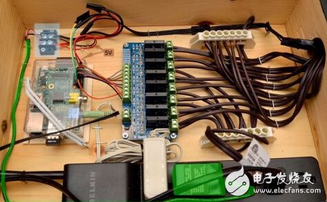
Step 4: Connect the Raspberry Pi and Relay Module
Disconnect all power (power and PI) and connect 5V to the bottom two external power connectors. I connected this dedicated 5 volt power supply to the power board, which made the Pi not drive the full load of the relay and could also drive the transistor and external power relay.
The location of GPIO0 is now determined by GPIO7. On this B-board:
GPIO0 = Pin 11
GPIO1 = Pin 12
GPIO2 = Pin 13
GPIO3 = Pin 15
GPIO4 = Pin 16
GPIO5 = Pin 18
GPIO6 = Pin 22
GPIO7 = Pin 7
Grounding feet are Pin 6, Pin 9, Pin 14, Pin 20, Pin 25
Since the connection of the SSR module is fixed, I trim each jumper to the appropriate length to match the spacing of these components. Connect all 8 input channels and the ground pin of the Pi.
Each channel has an LED corresponding to the SSR module, and the LED is illuminated when GPIO is high. Do a simple test to check all connections, attach test.py, and set each GPIO-7 high for two seconds.
Step 5: Cutting and preparing the extension cord
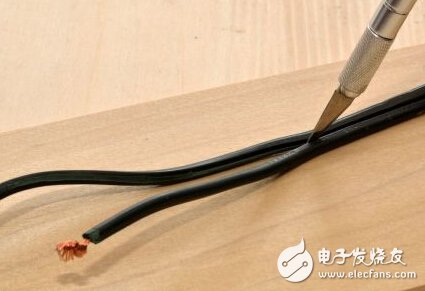
Each extension cord cuts off the plug end leaving the maximum usable length attached to the slot, which allows it to extend to the top of the tree. Cutting the plastic at the end of the spinal splitting wire maintains two joined sheets.
Mark the numbers 1 through 8 at the end of each slot with a pen mark so that it is easy to determine which socket corresponds to the SSR module channel. We also need a plug and some extra wires for the next step.
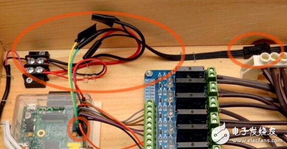
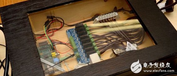
Step 6: Connect the AC extension cable
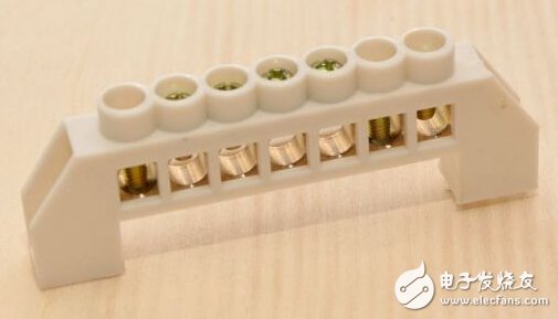
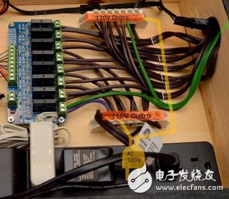
The next step is to hook the output of the SSR module and the 8 extensions. Because the number of wires is easily confused, I use the power distribution block and stapler to position these things.
Then power off, cut off the plug end of the previous step and plug it into the power strip. The other ends of the power board are connected to the top and bottom power distribution blocks, respectively, and the two ends are pinned.
Now connect the cut extension of the previous step. In this design, the housing has a 1.5-inch hole that allows all the wires to be worn out, so the green part is one of the jumpers that connects to the output of the terminal block and the SSR module. To complete the design of this circuit, we need a shorter wire (blue part in the figure) to connect to the other; the terminal block and the SSR module. The trim is then kept neat.
Step 7: Test the AC system
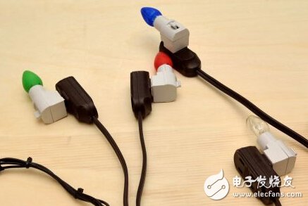
I installed it on all extension cords with a nightlight of just $1 and tested it. Test again with the test program that tested the SSR module before, making sure that each light is in place.
The light box indicates that each line can pass through a 0.34A circuit, and the two colored lights are only 0.68A. This is well below the 75-200V, 2A SSR level, although I still have to double-check the SSR module fuse to the board.
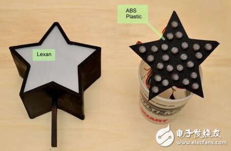
Step 8: Design the star
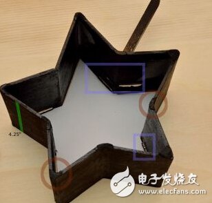

The first step was to design a printable template that can now be used to help shape wood frames and plastics. After scaling and printing the template to the right size, I used a piece of 4.25 x 0.125 inch wood.
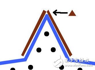
Place the template on the surface and hold two pieces of wood, such as the brown part of the picture. When the edges of the two blocks are in contact, they are bonded with glue. Then use a thin piece of wood to adjust the two pieces of wood and stick them to the star.
Due to the need for the production method, I had to wait a few hours before each joint glue dries before proceeding to the next one. After the entire star was completed, I filled the gap with a plasterboard. Some small plugs are then glued inside the star to position the LED assembly when inserted.
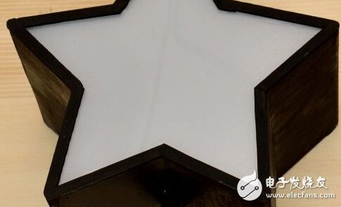
Place the assembled star on the Lexan plate, cut the Lexan by star, then check if it fits inside the wooden frame, then spray it on the Lexan side with 2 layers of white paint and let it dry for 24 hours.
In order to hide the lid of the Lexan star and wood frame, a 0.25 inch strip is required to reduce its shape and the gap between the "capping" frame and the light cover. Finally, the star is attached to the top of the tree with wooden sticks/studs.
Step 9: Make LED shape
Use the same template to form a wooden star, cut off the ABS plastic sheet to the right size, and insert Jupiter.
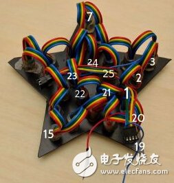
This template is then used here for drilling, for a total of 25 LED holes. Adafruit's LEDs have silicone outside, so they are best drilled into 12mm holes.
After doing work on the periphery of the star, move to the interior to complete the work. In my plan there is also LED position wiring as shown in the figure, 1 indicates the first LED connector.
Step 10: Design the star LED extension cable
Next, we're going to design an 8-foot cable that extends from the outer casing to the star on the top of the tree.
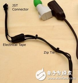
Trim 4 lengths of 8 foot wires, one end tied together with electrical tape to keep them neat.
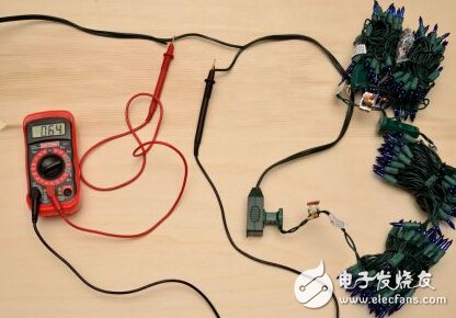
Solder the JST connector at either end of the bundled wire to connect the housing to the star. Make sure that the wires are in the correct position, after inserting them into the star, blue/green/yellow/red matches each other. Use a multimeter to check that the wires are wired correctly.
Step 11: Connect the star to the Raspberry Pi
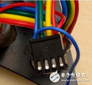
It is now necessary to design a socket in the housing for the star/extension line to be inserted.
Red = 5V; blue = ground
The power can be connected to the two lines of the JST connector terminal, and the power supply of the RaspberryPi is also connected.
The other two connections:
Yellow = Data = MOSI = PIN19
Green = clock = SCLK = PIN23
According to Adafruit's tutorial wiring. Both jumper cables are stripped at both ends so they can be soldered to the JST connector.
Step 12: Test the LED
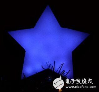

After the LED star is connected to the Pi, run a simple test procedure to ensure that the lights are illuminated properly. Most of the code comes from the AdaFruit Tutorial, including posts on the website forum. The color of the LED changes from pure blue to red during the test.
Step 13: Connect the speakers and cover the case
Install the speakers, control them with RaspberryPi, and plug in the power board. A simple drive speaker volume adjustment knob allows volume adjustment.
Because here I want to see the inside of the case, so I installed a piece of 8.5×11 glass on the top of the cover. A large portion of the enclosure has 110 VAC exposure, so safety protection is required.
Step 14: Hang the light on the tree

In order to produce different effects/impacts, I chose different channel arrangements.
Step 15: Loading music, software, and programs
- Electronic enthusiast network original compilation, reproduced please indicate from 39 °!
Measurement data can be sent via PufangTech`s RS485 Wireless Modem for point to point or point to multi-point data communication with a range of 1km to 50km. It provides a transparent half duplex radio serial connection wirelessly operating in VHF/UHF frequency band.
The parameters of the wireless modems can be configured through the local serial port using Windows based software. The individual configuration parameters can be stored on PC for future use.
PufangTech wireless modem equipped with LEDs which enable the operator to see at a glance the status of the modem and its interfaces. The LEDs provide the operator with a quick visual check and if the modem is in normal operation, configuration or alarm status.
RS485 Wireless Modem is developed for remote supervision and control applications. Typical target applications such as slave stations of oil, gas and water pipelines, environmental monitoring, street light control, wastewater pumping stations and OEM applications.
RS485 Wireless Modem
RS485 Wireless Modem,RS485 Wireless Data Radio Modem,RS485 Wireless GSM Modem,RS485 Wireless Router Modem
Shenzhen PuFang Technology Co., Ltd. , https://www.hytelus.com