As countries all over the world pay more attention to the requirements of energy saving and emission reduction, LED as a new light source is more and more widely used for its high efficiency and energy saving. The following mainly introduces the introduction of non-isolated technology in the LED driver application between 1-30W in the low power section.
A RC step-down:
1. The principle and application of RC Buck:
Capacitor buck actually uses capacitive reactance to limit current, and capacitor actually plays a role of limiting current and dynamically distributing voltage across capacitor and load.
2. Pay attention to the following points when using capacitor voltage reduction:
Choose an appropriate capacitor according to the current size of the load and the operating frequency of the alternating current, rather than the voltage and power of the load. The current-limiting capacitor must be a non-polar capacitor, not an electrolytic capacitor. And the withstand voltage of the capacitor must be above 400V. The most ideal capacitor is a polypropylene metal film capacitor. Capacitor buck can not be used in high power conditions, generally used in low power applications below 5W, capacitor buck is not suitable for dynamic load conditions, capacitor buck is not suitable for capacitive and inductive loads, suitable for single power LED drive applications Voltage application.
3. The basic circuit of RC-buck simple power supply is as follows (Figure 1)
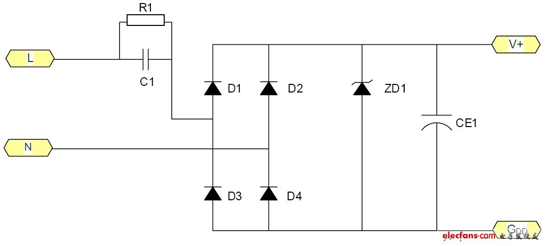
figure 1.
C1 is a step-down capacitor, D1, 2, 3, and 4 are bridge rectifier diodes, ZD1 is a zener diode, and R1 is the charge discharge resistance of C1 after the power is turned off.
4. Device selection
When designing the circuit, you should first determine the exact value of the load current, and then refer to the example to select the capacity of the buck capacitor. Because the current Io provided to the load through the buck capacitor C1 is actually the charging and discharging current Ic flowing through C1. The larger the capacity of C1 and the smaller the capacitive reactance Xc, the larger the charging and discharging current flowing through C1. When the load current Io is less than the charge and discharge current of C1, excess current will flow through the voltage regulator tube. If the maximum allowable current Idmax of the voltage regulator tube is less than Ic-Io, the voltage regulator tube will be easily burned. To ensure the reliable operation of C1, its withstand voltage selection should be greater than twice the power supply voltage. The selection of the bleeder resistor R1 must ensure that the charge on C1 is discharged within the specified time.
5. Calculation method of actual parameters:
It is known that C1 is 0.33μF and the AC input is 220V / 50Hz. Find the maximum current that the circuit can supply to the load.
The capacitive reactance Xc of C1 in the circuit is:
Xc = 1 / (2 πf C) = 1 / (2 * 3.14 * 50 * 0.33 * 10-6) = 9.65K
The charging current (Ic) flowing through capacitor C1 is:
Ic = U / Xc = 220 / 9.65 = 22mA.
Two linear drive circuit:
1. Typical circuit such as (Figure 2)

figure 2
2. Working principle:
R3 is a constant current resistor. The voltage drop of R3 is used to control the switch of TL432. The switch of 432 is used to control the conduction of Q1 to achieve the purpose of outputting a constant current. Loss on R3. The constant current value is 1.21 / R3. R1 is selected according to the magnification of Q1.
3. Notes on application:
This circuit is recommended for single-voltage input, small current output LED power drive, such as bulbs, T tube, etc., generally recommended output current is 100mA. At the same time, the closer the output voltage is to the input, the better, so as to avoid excessive voltage drop of Q1 and excessive loss, and low efficiency. Therefore, it is better to use LEDs in series.
Three constant current diode drive circuit
1. Typical circuit such as (Figure 3, Figure 4)
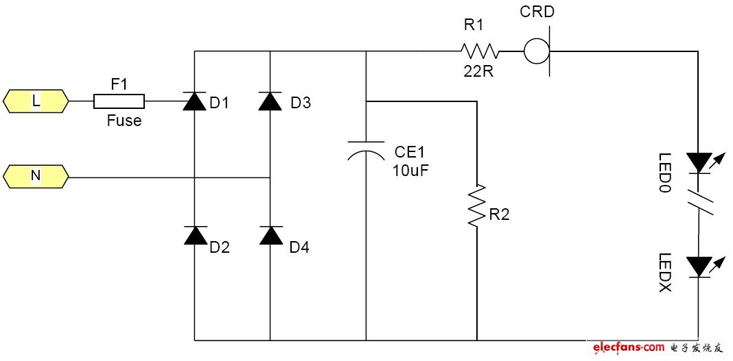
image 3
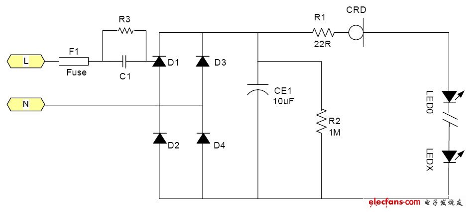
Figure 4
2. Working principle
The ideal constant current source is a device with an infinite internal resistance, regardless of the value of the voltage across it, the current flowing through it will never change. Of course, such a device cannot exist. The actual constant current diode is equivalent to a certain operating voltage range, such as 25-100V, its current is constant to a certain value, such as 20mA. Its equivalent circuit is shown in Figure 5.
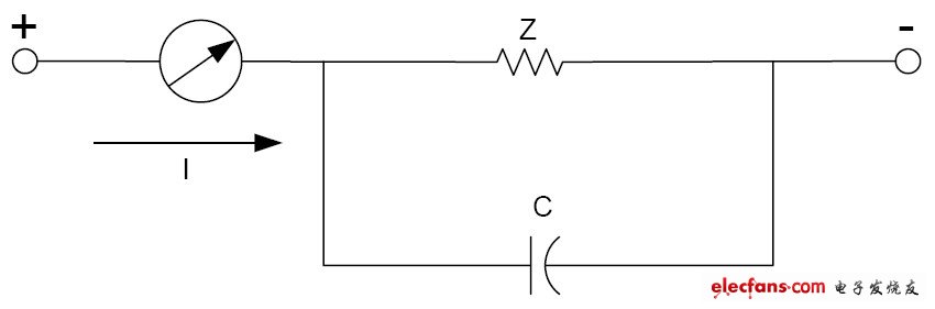
Figure 5
The internal resistance is Z, and the parallel capacitance is about 4-10pF. Its typical volt-ampere characteristics are shown in Figure 6.
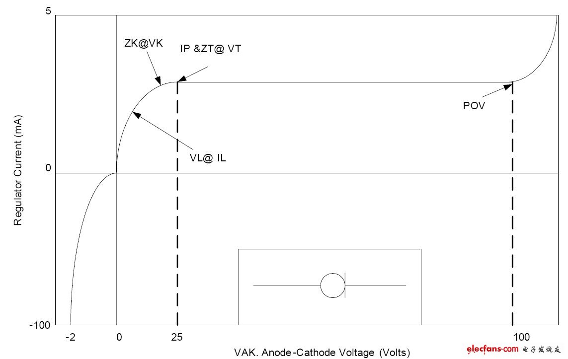
Image 6
It has a constant current interval within a certain voltage range. In this interval, the current flowing through it is almost unchanged. VL is the voltage value that reaches IL, and IL is about 0.8Ip.
3. Application considerations
Since the constant current diode needs a certain voltage Vk to enter the constant current, a power supply voltage that is too low cannot work. Usually this Vk is about 5-10V, so most battery-powered LEDs cannot work. The maximum current is limited due to the power consumption of the constant current diode, so excessive current is not suitable. For example, a 1W LED usually requires 350mA, and it is difficult to provide a constant current diode. At present, the more suitable use case is that the LED lamps powered by AC mains use many low-power LEDs in series, that is, the case of high voltage and small current is most suitable; The withstand voltage of the current diode has a certain limit, so the power supply voltage change it can absorb is also limited. Take the 100V withstand voltage CRD for 220V mains power supply, which can only deal with limited voltage changes. After 220V is bridge-rectified, its output DC voltage is about 264V. If the mains change + 10% ~ -15% is equivalent to 290 ~ 187V after rectification, the voltage change is 103V. It has exceeded its withstand voltage. Because of the non-linearity of LED volt-ampere characteristics, it is difficult to express it with a formula. In short, when the mains voltage decreases, the current in the LED will decrease as the mains voltage decreases. Its brightness will also change. In the typical application circuit, Fig. 3 is a typical application circuit, and Fig. 4 is a resistance-capacitance-reduction application circuit in order to cope with low-voltage output occasions.
2Pans Buffet Server,Buffet Server Warming Plate,Buffet Server Warmer,2Pans Buffet Server Warmer
Shaoxing Haoda Electrical Appliance Co.,Ltd , https://www.zjhaoda.com