There is no doubt that photovoltaic modules are one of the most important devices for photovoltaic power plants! This article will provide a comprehensive introduction to PV modules.
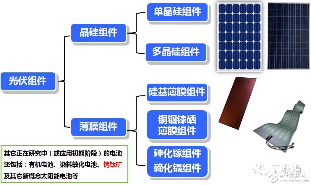
Classification of photovoltaic modules
Market share of different types of components in the past 10 years.
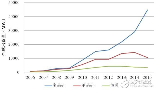
Figure 1: Shipment of various types of PV modules from 2006 to 2015
Internal structure of ordinary crystalline silicon components

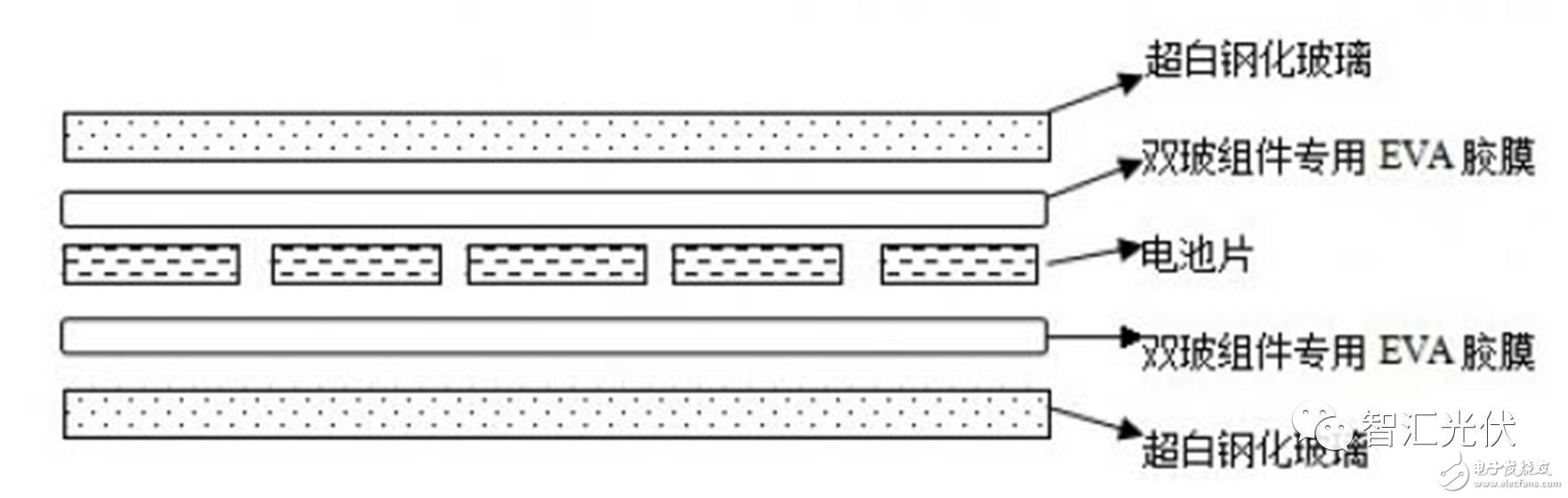
Internal structure of double glass components
Conversion efficiency of photovoltaic modules
1 power
We often say that 255Wp PV modules are used. The "p" in the table below is an abbreviation for peak, which means that its peak power is 255W. “Standard test conditions†are indicated in all technical specifications. The picture below shows a part of the technical specifications of Changzhou Tianhe's PV modules (250W, the same below).

The output power of the PV module is "nominal power" (250 W) only under standard test conditions (STC conditions, irradiance 1000 W/m2, battery temperature 25 ° C, AM = 1.5). When the irradiance and temperature change, the power will definitely change. In addition, the power error is plus or minus 3%, indicating that the actual power of the component is 242.5~257.5W. However, the power deviation of this component is a positive deviation of 3%.
Under non-standard conditions, the output power of PV modules is generally not the nominal power. The figure below shows the nominal power of 250W and 255W under NOCT conditions.

The irradiance is 800W/m2. When the battery temperature is 20°C, the output power of the 250W component is only 183W, which is 73.2% under the standard condition.
2 photoelectric conversion efficiency
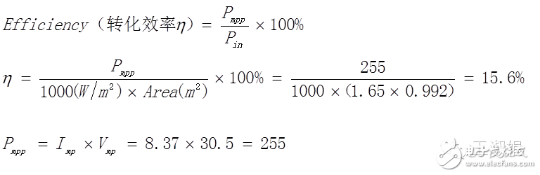
1) Calculation method of efficiency
In theory, the components of the same size and nominal power are definitely the same. The PV module consists of a cell. A PV module usually consists of 60 (6 & TImes; 10) or 72 (6 & TImes; 10) cells with an area of ​​1.638 m2 (0.992 m & TImes; 1.652 m) and 3.895 m2 (0.992 m & TImes). ; 1.956m).

When the irradiance is 1000 W/m2, the power received on the 1.638 m2 component is 1638 W, and when the output is 250 W, the efficiency is 15.3%, and at 255 W, it is 15.6%.
2) National standards for efficiency requirements
According to the "Comments on the Promotion of Market Function to Promote Photovoltaic Technology Progress and Industrial Upgrading" issued by the General Affairs Department of the National Energy Administration on February 5 (Guo Neng Ji Xin Neng [2015] No. 51):
Since 2015, PV modules and grid-connected inverter products used in state-subsidized photovoltaic power generation projects should meet the relevant requirements of the “Specifications for Photovoltaic Manufacturing Industry Standardsâ€, as shown in the following figure.

Taking the commonly used 60-piece polycrystalline silicon photovoltaic modules as an example, the conversion efficiencies of different specifications are as follows.

Therefore, after 2015, it is necessary to use more than 255W of PV modules to obtain state subsidies; PV modules above 270W can be regarded as “leadersâ€.
3 voltage and temperature coefficient

The voltage separates the road voltage and the MPPT voltage, and the temperature coefficient is divided into a voltage temperature coefficient and a power temperature coefficient. In the design of the series-parallel scheme, the open circuit voltage, the operating voltage, the temperature coefficient, and the local extreme temperature (preferably the daytime) are used to calculate the maximum open circuit voltage and the MPPT voltage range to match the inverter.
Several factors affecting the output of photovoltaic modules
1 hot spot effect
The solar cell module that is shielded in a series branch will be used as a load to consume the energy generated by other illuminated solar cell components. The shaded solar cell component will heat up at this time, which is the hot spot effect.
This effect can seriously damage the solar cell. Part of the energy generated by a solar cell with light may be consumed by the obscured battery. The hot spot effect may be just a piece of bird droppings.
In order to prevent the solar cell from being damaged by the hot spot effect, it is preferable to connect a bypass diode between the positive and negative terminals of the solar cell module to prevent the energy generated by the illumination component from being consumed by the shielded component. When the hot spot effect is severe, the bypass diode may be broken down, causing the component to burn out, as shown below (picture from TUV-Rheinland).

2 PID effect
Potential Induced Degradation (PID) is a battery component that has a long-term under high voltage, causing leakage current between the glass and the packaging material. A large amount of charge is slammed on the surface of the cell, which deteriorates the passivation effect on the surface of the cell, resulting in components. Performance is below design standards. When the PID phenomenon is serious, it will cause a component to attenuate more than 50% of the power, thus affecting the power output of the entire string. High temperature, high humidity, high salinity coastal areas are most prone to PID phenomenon.
There are three main reasons for the component PID phenomenon:
1) System design reasons: The lightning protection grounding of PV power plant is realized by grounding the component frame at the edge of the square array, which causes a bias voltage to be formed between the individual components and the frame. The higher the bias voltage of the component occurs, the PID phenomenon occurs. The more serious it is. For the P-type crystalline silicon component, the anode of the inverter with the transformer is grounded, and the forward bias of the component frame relative to the cell is eliminated, which effectively prevents the occurrence of the PID phenomenon, but the grounding of the negative pole of the inverter increases the corresponding system construction. cost;
2) Photovoltaic module causes: The high temperature and high humidity environment causes leakage current between the cell and the ground frame, and a leakage current channel is formed between the package material, the back plate, the glass and the frame. By using the modified insulating film ethylene vinyl acetate (EVA) is one of the ways to achieve component anti-PID, the component's anti-PID performance will be different under different EVA encapsulation film conditions. In addition, the glass in the photovoltaic module is mainly calcium soda glass, and the influence of glass on the PID phenomenon of the photovoltaic module is still unclear;
3) Cell reasons: The uniformity of the cell sheet resistance, the thickness of the anti-reflection layer and the refractive index have different effects on the PID performance.
In the above three aspects of causing the PID phenomenon, the component PID phenomenon caused by the potential difference between the component frame and the component in the photovoltaic system is recognized by the industry, but the mechanism of the PID phenomenon generated by the component in both the component and the battery is not yet Clearly, the corresponding measures to further improve the anti-PID performance of components are still unclear.
3 cell crack
The crack is a defect in the battery. Due to the nature of the crystal structure, crystalline silicon cells are very susceptible to cracking. The process flow of crystalline silicon module production is long, and many parts may cause the cell to crack. According to the information of Xi'an Jiaotong University Yang Hong, there are about 200 reasons in the battery production stage. The essential cause of cracking can be summarized as mechanical stress or thermal stress on the silicon wafer.
In recent years, in order to reduce the cost, crystalline silicon cell manufacturers have been developing in a thinner and thinner direction, thereby reducing the ability of the cell to prevent mechanical damage.
In 2011, Germany's ISFH published their findings: according to the shape of the cell crack, it can be divided into five categories: tree cracks, synthetic cracks, oblique cracks, parallel to the main grid lines, perpendicular to the grid lines and throughout the entire Crack in the battery.
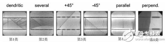
Figure: Crystal silicon cell crack shape
Different cracks have different effects on the function of the battery. The most influential factor on the function of the cell is the crack (parallel 4) parallel to the main gate line. According to the results of the study, 50% of the failed sheets are from cracks parallel to the main grid lines. The efficiency loss of a 45° oblique crack (Category 3) is 1/4 of the loss parallel to the main grid line. Cracks perpendicular to the main gate line (Category 5) hardly affect the fine grid lines, thus causing the area of ​​the cell failure to be almost zero.
Studies have shown that when the failure area of ​​a single cell in a component is less than 8%, the power of the component is not affected much, and 2/3 of the diagonal stripes in the component have no effect on the power stability of the component.
Photovoltaic module performance testing
After the PV power plant is running for a period of time, it needs to be tested to determine the performance of the PV power plant. Involving photovoltaic modules, mainly including the following items.
1 power attenuation test
What is the decay rate of PV modules after 1 year and 25 years of operation? For 25 years, it may not have been running for such a long time. According to national standards, the 2-year decay rate of crystalline silicon cells should be within 3.2%. But at present, this data is really hard to say for three reasons:
1) The output power of PV modules is calibrated with laboratory standard light source and test environment, but it seems that there are certain differences in the standard light sources of different manufacturers in China. The 250W component calibrated at plant A, to plant B, may be the 245W component.
2) The accuracy of the instrument used for on-site inspection is poor. It is said that the error within 5% is acceptable. With an error of 5% of the instrument, measuring 2% (1 year) of attenuation, the difficulty is somewhat large, and the results are also doubtful.
3) The test conditions on site are quite different from those in the laboratory, which is just too little at 1000W/m2 and 25°C! Therefore, a conversion of a test value to a standard value is required, and the output power is positively correlated with the irradiance only in a small interval. As shown in Fig. 2, even at 800 W/m2, it is not positively correlated. Therefore, there must be errors in the conversion.
In addition, many components may be -3% power deviation, not attenuated, 3% is gone...
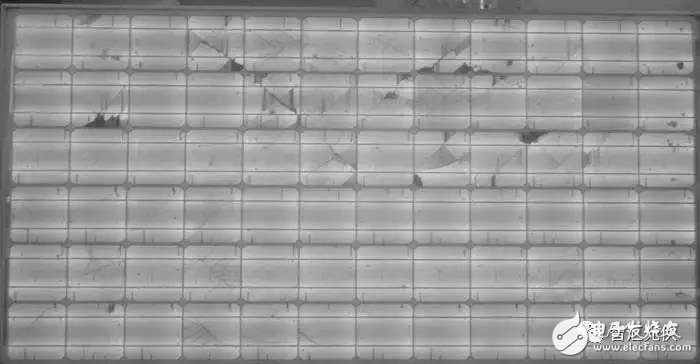
2 EL test
When there is a problem with the photovoltaic module, the local resistance increases and the temperature in the region increases. Like the X-ray machine in our physical examination, the EL tester can perform physical examination on PV modules - through infrared image capture, the images appear different colors depending on the temperature, so it is very easy to find many problems of PV modules: crack , hot spots, PID effects, etc.
In the process of transportation, handling, installation, etc., the photovoltaic module is easily stepped on and impacted, resulting in the component being invisible and cracked, which greatly affects the output power of the component. It can be detected by EL, as shown below.
The picture below shows the infrared image of the hot spot phenomenon (picture from TUV-Rheinland), and the red dot is the part where hot spots are generated.
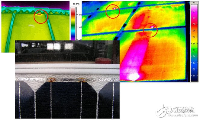
The picture below shows the infrared image of the PID effect, and the battery with serious PID effect is black.

In addition to the above tests, the visual inspection of the components is also very important. Such as component back plate scratches, yellowing, bubbling, connectors falling off, etc.
Recent PV module price changes
Photovoltaic power plants are affected by the policy and will be put into production in a certain period of time. As a result, the demand for upstream in the year has changed dramatically. The chart below shows the PV module price curve for the last 30 weeks (June 2016~February 2017).
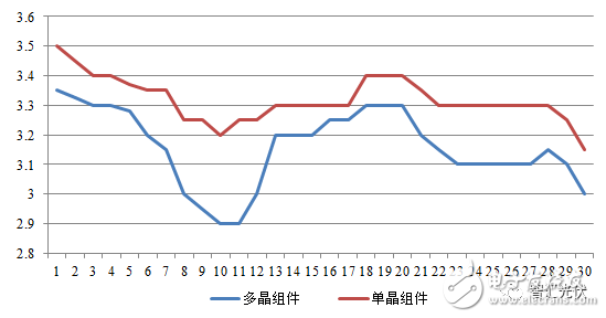
Before 2016 SNEC (before May), the price of polycrystalline PV modules has been maintained at around 3.8 yuan / W, and after 10 months, more than 10%; when the tender in August, the price of 3.05 yuan / W,
It is expected that the price price will drop rapidly after 630 in 2017 and is expected to be within 2.5 yuan/W.
The load pin is a shaft equipped with a Wheatstone bridge to measure double shear deformation. Some manufacturers design their load pins in single shears for cost reasons.
The load pin design clearly has the benefit of integrating itself into the system, ensuring a mechanical interface between the components and providing information about the applied force. The most common example is the U-shaped pin installed on the end anchor point or the upper pulley/Balance beam of the EOT crane, which is used to suspend the chain hoist on its trolley, on the sheave of the winch, and the head of the hydraulic cylinder. Used to hang lighting and other equipment in theaters or concert halls.
The design principle relies on managing the reduced load pin diameter in the separation area between the holding plate (flange) and the center tool where the main effort is applied. The purpose of these reduced diameters is to create a deformation zone where the strain gauge will be placed to ensure sufficient strain concentration, thus ensuring accuracy and repeatability.Double / Triple Sensor,Load Pin,Torque Axis,Extensometer,Chinese Sensor,Traction / Compression Sensor,Torque,Extended Double Measurement Sensor
load Pin, Torque Axis, Traction / compression sensor, extensometer, Double / triple sensor, Extended double measurement sensor
Ningbo Santwell Imp & Exp Co.,Ltd , https://www.santwell.com