Many people have already recognized the harmful effects of inverters on motors. For example, in a water pump factory, over the past two years, customers frequently reported that pumps were damaged during the warranty period. Previously, the quality of this factory’s pumps was highly reliable. After investigation, it was found that these damaged pumps were driven by inverters.
Although the issue of inverter-induced motor damage is gaining more attention, there remains a lack of understanding about the underlying mechanisms and effective prevention methods. This article aims to clarify these concerns and provide practical solutions.
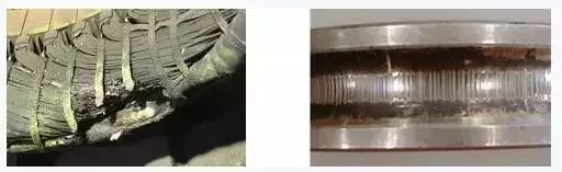
The damage caused by inverters to motors can be categorized into two main types: stator winding damage and bearing damage, as shown in Figure 1. These issues typically occur within a few weeks to ten months, depending on various factors such as the inverter brand, motor brand, motor power, inverter carrier frequency, cable length between the inverter and motor, and ambient temperature.
Early motor failures due to inverter usage can lead to significant economic losses for production. These losses are not only related to repair or replacement costs but also include downtime expenses. Therefore, when using an inverter to drive a motor, it is essential to pay close attention to the risk of motor damage.
**The difference between inverter drive and power frequency drive**
To understand why motors are more prone to damage under inverter conditions, it's important to first grasp the differences between inverter voltage and power frequency voltage. Then, we can see how this difference negatively affects the motor.
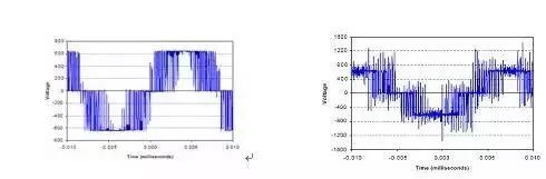
The basic structure of an inverter includes a rectifier circuit and an inverter circuit. The rectifier circuit produces a DC voltage using diodes and a filter capacitor, while the inverter circuit converts this DC voltage into a pulse width modulated (PWM) voltage waveform. As a result, the voltage supplied to the motor is a pulsed waveform rather than a sine wave. This pulsed voltage is the primary cause of motor damage.


When the pulsed voltage is transmitted through the cable, if the cable impedance does not match the load impedance, reflections occur at the motor end. These reflections combine with the incident wave to form a higher voltage, which can reach up to twice the DC bus voltage, or approximately three times the input voltage of the inverter, as shown in the figure. This excessive voltage spike can damage the stator windings, leading to premature motor failure.
The lifespan of an inverter-driven motor after experiencing a voltage spike depends on several factors, including temperature, pollution, vibration, voltage, carrier frequency, and insulation condition.
Higher inverter carrier frequencies result in a current waveform closer to a sine wave, reducing motor operating temperature and extending insulation life. However, a higher carrier frequency means more voltage spikes per second, increasing stress on the motor. Figure 4 illustrates the relationship between insulation life, cable length, and carrier frequency. As shown, for a 200-foot cable, increasing the carrier frequency from 3 kHz to 12 kHz reduces insulation life from 80,000 hours to 20,000 hours.
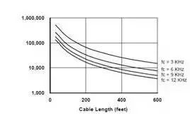
**Effect of carrier frequency on insulation**
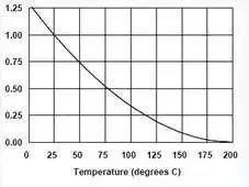
Higher motor temperatures shorten insulation life. As shown in Figure 5, when the temperature reaches 75°C, the motor life is reduced to 50%. Inverter-driven motors generate more high-frequency components, resulting in higher operating temperatures compared to those driven by power frequency voltages.


The reason inverter damage occurs in motor bearings is due to current flowing through the bearing. This current intermittently completes a circuit, generating an arc that burns the bearing.
There are two main reasons for current flow through AC motor bearings: induced voltage from electromagnetic field imbalance and high-frequency current paths from stray capacitance.
In an ideal AC induction motor, the magnetic field is symmetrical. When the three-phase winding currents are equal and phase-shifted by 120°, no voltage is induced on the motor shaft. However, PWM voltage from the inverter can create an asymmetrical magnetic field, inducing voltage on the shaft. This voltage, ranging from 10–30 V, is proportional to the driving voltage.
When this voltage exceeds the insulation strength of the bearing lubricant, a current path is formed. During rotation, the lubricant periodically blocks the current, acting like a mechanical switch and causing arcing, which damages the shaft, balls, and bearing surface.
If there is no external vibration, the small pits may not be significant. However, with vibration, grooves can form, severely affecting motor operation.
Additionally, experiments show that the shaft voltage is related to the inverter output fundamental frequency. Lower fundamental frequencies result in higher shaft voltages and more severe bearing damage.
At the start of motor operation, when the lubricant temperature is low, the current is around 5–200 mA, which typically doesn’t cause damage. However, as the motor runs longer and the lubricant temperature rises, the peak current can increase to 5–10 A, causing arcing and forming small pits on the bearing components.
**Motor stator winding protection**
When the cable length exceeds 30 meters, modern inverters inevitably generate voltage spikes at the motor end, shortening its life. To prevent motor damage, two main approaches are used: installing a motor with higher insulation resistance (often called a variable frequency motor) or implementing measures to reduce peak voltage. The former is suitable for new installations, while the latter is ideal for retrofitting existing motors.
Currently, there are four common motor protection methods:
1) Installing a reactor at the inverter output: This method is widely used, but it is most effective for shorter cables (less than 30 meters). It may not always be ideal, as shown in Figure 6(c).
2) Installing a dv/dt filter at the inverter output: This is suitable for cables under 300 meters. It is slightly more expensive than a reactor but offers better performance, as seen in Figure 6(d).
3) Installing a sine wave filter at the inverter output: This is the most ideal solution. It converts the PWM voltage into a sine wave, allowing the motor to operate as if it were under power frequency voltage. This completely eliminates the problem of voltage spikes, even with long cables.
4) Installing a peak voltage absorber at the cable-motor interface: While reactors and filters have their benefits, they can be large, heavy, and costly for high-power motors. Additionally, they cause voltage drops that affect motor torque. The peak voltage absorber overcomes these issues.
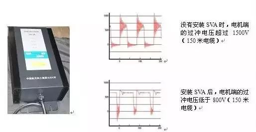
The SVA (Spike Voltage Absorber) developed by the Second Hospital of the Aerospace Science and Industry Group is an advanced device that uses power electronics and intelligent control technology to protect motors from damage. It also safeguards the motor bearings.

The SVA is a new type of motor protection device, as shown in Figure 7 (Aerospace SVA model). It is connected in parallel with the motor’s power input.
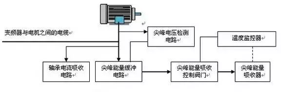
The working process of the SVA is as follows:
1) The peak voltage detection circuit monitors the voltage amplitude of the motor power line in real time.
2) When the detected voltage exceeds a set threshold, the spike energy buffer circuit absorbs the spike energy.
3) Once the buffer is filled, the spike absorption control valve opens, directing the energy to the absorber, where it is converted into heat.
4) The temperature monitor ensures the absorber doesn’t overheat by adjusting the absorption valve when necessary, without compromising motor protection.
5) The bearing current absorption circuit protects the motor bearing by absorbing the bearing current.
Compared to other motor protection methods like the dv/dt filter or sine wave filter, the SVA offers advantages such as compact size, lower cost, and easy installation (parallel connection). Especially for high-power applications, the SVA excels in terms of price, size, and weight. Moreover, since it is installed in parallel, it does not cause a voltage drop, unlike the dv/dt filter and sine wave filter, which can reduce motor torque.
Zooke Connectors Co., Ltd. , https://www.zooke.com