Principles of image compression encoding and decoding
This section introduces the basic principles of image compression coding and the basic structure of image data compression and decompression circuits. They are the basics of looking at the circuit diagram of a DVD player.
1. The basic method of image compression The amount of image data is extremely large, and the total amount of data must be greatly compressed before it can be stored on a disc with a diameter of 12 cm. In practical technology, the total amount of image data can be compressed in the following ways.
1. Adopt brightness (Y) and chroma (C) sampling methods. Practical color TV technology does not transmit and process red, blue, and green primary color signals, but transmits and processes luma signal Y and chroma signal C. This processing method is conducive to achieving compatibility between color TV and black and white TV, and is also beneficial to limit the bandwidth of color TV signals. In the digital image processing technology, the method of transmitting and processing the luminance signal Y and the chrominance signal C is still used. Since human eyes are sensitive to brightness information and not sensitive to color information, they are transmitted with higher resolution for Y signals and lower resolution for C signals. The actual method is as follows: transmit each luminance Y pixel; and decompose the chromaticity C into U and V color difference signals (or write as Cb, Cr, BY, RY), and transmit separately; Sampling point by point, and less sampling of chroma C. That is, corresponding to 4 luminance sampling points, only one point is sampled for the chrominance signal, that is, the sampling for U and V pixels is low, and each sampling point is taken. This sampling format is called the YUV411 format.
After adopting the YUV411 sampling format, its total data volume will be reduced by half compared to the three primary color sampling format. If three primary color sampling methods are used, each primary color should be the same as the luminance signal sampling method, that is, a point-by-point sampling method is adopted for each red, green, and blue. When using Y and C transmission methods, the number of samplings is reduced by half, and the number of digital transmissions is also reduced by half. The human eye is less sensitive to chroma. Taking advantage of the physiological visual characteristics of the human eye, people do not feel the image sharpness drop in subjective perception. Obviously, this is a powerful measure to compress the image data rate.
2. When the whole image is divided into small areas for segmentation processing, and data processing is performed on the image, segmentation processing is performed for each frame image. First, the image is cut horizontally into several pieces, and each piece is called a piece. Each piece is cut vertically into several pieces, called macroblocks. Macroblocks are the basic unit of image compression. The color image of each macroblock can be represented by one luminance signal Y and two color difference signals Cb, Cr (ie U, V), or each macroblock is divided into three layers, one layer of brightness Y, two layers of color Degrees (each Cb, Cr) are collectively called a macroblock.
Due to the different subjective sensitivity of human eyes to brightness and chroma, the brightness macroblock is usually divided into 4 blocks on average, and each small block is called an image block or block. See schematic diagram 2.2.1 for details. Each block can be further divided, called pixels or pixels, and pixels are the smallest unit that constitutes an image. For digital images, each pixel serves as a sampling point and has a corresponding sampling value. It can be seen that the finer the image segmentation, the more pixels, and the more sampling points, the higher the image clarity; conversely, the fewer the pixels, the lower the image clarity. In fact, the image compression process is to compress the image block data and pixel data. 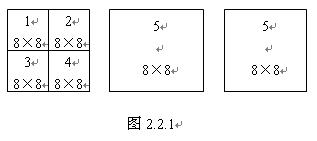
Depending on the color TV system, the specific data of the split image will change. For example, the PAL system, most of which are 625-line scanning standards, then each frame of the image is cut into 18 slices, each slice is then cut into 22 macroblocks, that is, each frame of the image is divided into 396 macroblocks; and the 525-line NTSC system, each The frame image is cut into 15 pieces, and each piece is cut into 22 macro blocks, that is, each frame image is divided into 330 macro blocks. For the luminance signal, each macro block is divided into 4 blocks, each block contains 8 × 8 = 64 pixels, then each macro block contains 256 pixels. However, for the two color-difference signals, the number of pixels in the macro block is equal to the number of pixels in the block, that is, the number of pixels is 8 × 8 = 64, which is 1/4 of the luminance pixel. Although the two-color-difference signal has fewer pixels and low definition, it does not affect the subjective perception of human eyes. When performing digital image processing, the 8 × 8 blocks (64 blocks in total) in the figure are arranged in order, and then processed in order according to the number order. That is to say, the block of 8 × 8 pixels is used as the basic operation unit, and the sampling value of each pixel (ie, sampling point) is processed in sequence.
3. Adopt inter-frame and intra-frame data compression technology.
Practical TV transmits 25-30 frames per second, so that the picture changes with a sense of continuity. The TV moving image is composed of a series of pictures with little difference between the frames. The slight change of each frame of the picture is mainly manifested in the main part of the picture, and the background difference of the picture is very small. The image is described by the luminance and chrominance information. In the adjacent frame images, if the luminance and chrominance signals of the same relative position are compared, the difference is usually small. After a lot of statistics, it is found that only 10% or less of the pixels in each pixel have a difference in brightness that exceeds 2% of the previous time, while the difference in chroma is less than 0.1%. There is a lot of repetitive content in each frame image, and the data of these repetitive content is redundant (redundant) information. Therefore, the method of reducing the time-domain redundant information, that is, the operation of inter-frame data compression technology to reduce the number of image transmission rate.
After analysis, it is found that there is quite a lot of redundant information in the same frame. The most sensitive part of the image and the eyes should be processed accurately and in detail, and each pixel needs to be finely transmitted; but for the non-main part of the image and the insensitive parts of the eyes, it can be roughly processed, that is Compression of information data. Therefore, according to the specific distribution of the image content of a frame, different data amounts can be used for transmission at different locations, reducing the data amount of the transmitted image and compressing the image data. This method of compressing data is to compress data in different spatial parts of the same frame image, which is called spatial domain redundant compression. For example, there is a portrait picture, the lines of the face and the head can be different in sharpness, especially the eyes and lips are rich in expression, the lines are more delicate and complex, which is the most attention to the audience, and should be transmitted with high definition; For the parts and cheeks, the outline changes less and the gray level changes less, so the audience pays less attention to these parts. Obviously, the main parts of the image, the parts with large changes in gray level, and the sensitive parts of the human eye, should be finely transmitted with a large amount of data; while the secondary parts of the image, the parts with small changes in gray level, human For the parts that the eyes don't pay attention to, they can be roughly transmitted with a smaller amount of data, or even only their average brightness information.
The following specifically discusses the data compression principle of digital images. First discuss the data compression technology of still images, that is, intra-frame data compression technology; then discuss the data compression technology of moving images, that is, inter-frame data compression technology.
Second, the intra-frame data compression technology first performs segmentation processing on the entire image, and obtains the minimum operation unit after segmentation. The following is based on the block composed of 8 × 8 = 64 pixels. Each pixel value can be sampled according to a certain rule. For example, the brightness value of each pixel can be sampled. If each pixel is quantized by 8bit, the total data amount of each block is 8bit × 64 (pixels), that is, 512bit . It can be seen that the amount of data after quantization of each pixel of the whole picture is very large, and data compression is required. Generally, after discrete cosine transform, zigzag scanning, variable length encoding and other processing procedures, the total amount of data can be compressed in a large amount.
1. Discrete Cosine Transform (DCT) coding
(1) Function description The discrete cosine transform is abbreviated as DCT (abbreviation of English Discrete Cosine Transform), which is a digital processing method and is often used for data processing. DCT is one of a variety of digital transformation methods. It is a method for transforming spatial domain images into frequency domain for analysis. Since the base vector formed by the transform kernel of the DCT has nothing to do with the content of the image, and the transform kernel can be separated, both the two-dimensional DCT can be completed with two one-dimensional DCTs, which greatly simplifies the difficulty of the mathematical operation. Fast algorithm makes DCT coding widely used. Applying DCT to image data compression can reduce the digital information representing the brightness (or chroma) level of the image and achieve the purpose of data compression. The use of DCT not only encodes the image, but also finds the location of the image details during the coding conversion process, so as to delete or omit the visually insensitive parts, and more prominently the visually sensitive parts, by selecting the main data to transmit and value the image .
The use of DCT to compress image data is mainly based on the statistical characteristics of the image signal in the frequency domain. In the space domain, the content of the image is very different; but in the frequency domain, after statistical analysis of a large number of images, it is found that the main component of the frequency coefficient of the image after DCT transformation is concentrated in a relatively small range, and is mainly located in the low frequency part. After the DCT transform reveals this pattern, some measures can be taken to discard the less energy part of the spectrum, and the main frequency components in the transmission spectrum should be kept as much as possible to achieve the purpose of image data compression.
(2) Laws and characteristics â‘ The spectrum of the time domain signal For a waveform that changes with time, it is a periodic signal that changes with time. It is a DC average value of a waveform with a certain amplitude value. The fundamental wave is superimposed with countless harmonics. The amplitude of the fundamental wave is the largest, and then the amplitude of each harmonic gradually decreases. The higher the harmonic superposition times, the closer the synthesized waveform is to an ideal rectangular wave. This analysis method is an increasingly widely used spectrum analysis method. Among them, the amplitude value of each sine wave harmonic is often called the spectrum coefficient. The spectrum coefficients are arranged together to form a coefficient column. The above facts show that the periodic rectangular wave can be described by the time domain (reflecting the amplitude-time relationship) or the frequency domain (amplitude-frequency relationship). The two have a corresponding relationship. In fact, various signals in the time domain can be described by the laws of the frequency domain. There is an inherent relationship between the two description methods, which can be converted to each other.
â‘¡Spectral coefficients of spatial domain signals For signals distributed in various spatial domains, similar frequency transformation can also be performed, that is, transforming spatial domain signals into frequency domain signals. DCT is one of the frequency analysis methods. Refer to Figure 2.2.2 to explain the DCT transformation process.
Take a block from the image and divide it into a 64 grid array of 8 × 8 pixels, that is, change from figure (a) to figure (b). After sampling the pixel-by-pixel brightness (or discussion of chroma) values, and listing the pixel brightness values ​​in a matrix, see Figure (C). Then use discrete cosine transform (DCT) to transform each spatial sample value 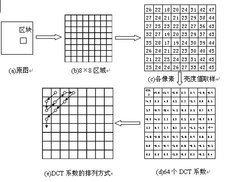
It is the value in the frequency domain, which is called DCT coefficient here.
For the above 64-point array, 64 DCT coefficients can be obtained and converted into a rectangular array table in figure (d). It has transformed an array of 64-point image sampling values ​​into a 64-point array consisting of a DC average and 63 cosine wave amplitudes of different frequencies, and is called a DCT coefficient array. After the above transformation, the data of spatial coordinates has been converted into data of frequency coordinates, namely DCT frequency coefficients. After sampling and quantizing the value of each pixel in the original 8 × 8 block, it is transformed into the frequency domain image signal spectral coefficients, which can be expressed by 64 frequency coefficients. The signal corresponds to one of 64 independent two-dimensional spatial frequencies. These spatial frequencies are composed of the "spectrum" of the input signal. Among the obtained 64 transform coefficients, the first term represents the DC component, that is, the average value of 64 spatial image sample values, and the remaining 63 coefficients represent the amplitude of each base signal.
Observing the data in Figure 2.3.2 (d), we can find the law. The value in the upper left corner of the matrix is ​​larger, while the value in the lower right corner is smaller, and it approaches zero. Therefore, the DCT coefficients of the base signals can be listed in a table in the zigzag scanning order. The specific trajectory of Z-shaped scanning is shown in Figure 2.3.2 (e). According to this rule, the DCT coefficients are arranged into data series, which becomes the DCT coefficient coding order. After the above processing, the two-dimensional data volume has been converted into one-dimensional data volume. The first item in the series is the average brightness value of the block. The distribution and size of the following coefficients can reflect the intensity of the fluctuation of brightness. If the coefficient is large, it means that the brightness fluctuation is large, and the image contour in this area is more detailed; if the value is small, it means that the brightness change in the area is relatively smooth; if the value is zero, it means that the high frequency component in the sequence is zero, and the brightness level No change. In the actual data processing process, the coefficient values ​​in the back are basically zero or tend to zero. The 63 coefficient sets and changes can reflect the details of the image in the block, that is, the image clarity.
Figure (d) matrix values ​​are very practical. The upper left corner has a larger value, which represents the DC component and low frequency component of the image information. It is the main part of the image information and the main part of the information in the block; while the lower right corner has a smaller value, which represents the high frequency of the image information The amplitude of the component is relatively small, which mainly reflects the details of the image. The human eye has high relative sensitivity to the brightness information of the image and is not sensitive enough to the color information of the image; also, the human eye has high visual sensitivity to the low-frequency components of the image information. The data series formed by scanning the zigzag characters just form a good correspondence with the sensitivity of human eyes to image information. According to the above laws of visual physiology, image data can be compressed.
2. Requantization of DCT coefficients The frequency data processed by the above DCT can be reprocessed to further compress the amount of data. The sensitivity of human eyes to various frequencies is different, and statistical sensitivity values ​​can be obtained. In this way, different conversion values ​​can be set for each frequency component, and the aforementioned converted DCT coefficients can be converted again to further highlight the components with large visual effects and weaken or ignore the components with small visual effects. This processing method is called quantization processing, or Q processing for short. For 64 coefficients in a 64-point array, corresponding to 64 different frequencies, 64 different conversion values ​​can be used. These 64 conversion values ​​are usually called quantization tables, and each conversion value is called a quantization step, or quantization value. In the 64-point array, the data quantization value in the upper left corner is smaller, and the data quantization value in the lower right corner is larger. The re-quantization of DCT coefficients can be implemented using a quantizer circuit. The circuit can divide the 64 coefficients of the block by the corresponding position quantization step size in the quantization table, and then round off to obtain 64 data values ​​after requantization.
After the quantization process, the coefficient value with a large quantization value has a small quotient value, that is, the data compression is relatively large, and the corresponding part of the original image has more ignored content; Small, the corresponding part of the original image is not ignored or minimally ignored. Therefore, the DCT coefficient matrix after quantization may have many zero values. Generally, the quotient of the data in the upper left corner is non-zero, and the quotient of the data in the lower right corner is very small, and can be abbreviated as 0 after rounding to the whole value. Many 0 values ​​appear on the coefficient matrix, which greatly reduces the amount of data. On the one hand, the main part of the image information is retained, on the other hand, the image data is greatly compressed.
3. Variable length coding (VLC)
The coefficient matrix after quantization has many 0 values. If zigzag scanning is performed, the following coefficients will also appear to have consecutive 0s. At this time, the total amount of data transmission has been significantly reduced, but the code bits have not decreased, still 64 coefficient bits. In order to further compress the total amount of data, variable-length coding can be used, also referred to as VLC (Variable Length Coding).
Generally, two methods are used for variable length coding. The first is to assign codewords of different lengths to replace data based on the frequency of data occurrence. For frequently occurring data, assign shorter codewords, and those that do not appear frequently will be given longer codewords. After this processing, the total bit rate of transmission can be reduced. The second method, although the Z-shaped scan causes multiple 0 values ​​to appear at the end of the coefficient column, there is no need to transmit the 0 values ​​bit by bit, only the "number" code of table 0 needs to be transmitted, and it will be restored as required after playback It is 0 bits to fill the 64 bits of the matrix. For example, 00000, it can be expressed as 50, and it is restored to 00000 during decoding.
In short, for still pictures, the use of discrete cosine transform, zigzag scanning, quantization processing and variable length coding methods can greatly reduce the amount of image data. During data decoding, variable length decoding is first performed to restore the fixed length of the data; then the coefficients are inversely quantized to restore the original DCT frequency coefficients; and then subjected to inverse discrete cosine transform to restore the spatial coordinate values ​​of the image, That is the data of the original image.
3. Inter-frame data compression technology For moving images, the images of adjacent frames have a strong correlation. When saving and recording dynamic images, it is not necessary to record and save all the information of each frame of image. You can record all the data of the first frame of the previous image and treat it as a static image, which can be compressed with static image data Method to deal with. In the subsequent frames, only the information that differs from the previous frame can be recorded. Therefore, during playback, the image of the following frame can be recovered by using the difference data of the image of the previous frame and the difference data of the following frame. This processing method saves a lot of data.
1. According to the MPEG-1 standard, the three pictures can be divided into three types. The first type is the first frame of the scene after the scene is changed. It is an independent picture. This picture is transmitted using the point-by-point sampling method of higher resolution. This picture is called the I picture (intra code frame, or Called intra-coded frame). The picture information is determined by its own picture, without reference to other pictures. The data of this screen represents the main content and background content of the moving image, and it is the basis of the TV screen. The second type is a picture that has changed significantly from the I picture at a certain time and the main position of the moving image has changed on the same background. This picture is called the P picture (predicted frame, or forward predictive coded frame). This picture uses the previous I picture as a reference picture. This picture does not transmit repetitive information such as background, and only transmits the difference of the main body change. This omits part of the detailed information, and relies on the frame memory to rely on the main content of the I picture during playback. The difference between the part and the P picture can be calculated to obtain the complete content of the new picture. It is an actual picture with both a background and a current moving subject state. The third kind, the situation is similar to the P picture, is used to transmit the picture between the I and P pictures, called the B picture (bidirectional prediction frame, or bidirectional prediction interpolation coding frame). This picture only reflects the change of the moving subject between the I and P pictures, and uses displacement vectors (or motion vectors, etc.) to indicate the movement of the picture subject. The amount of information is smaller. Because it can be referred to both I-picture content and P-picture content when it is played back, it is called a bidirectional prediction frame.
After dividing a series of consecutively related pictures into I, P, and B types, the amount of transmitted information is significantly reduced. In the P and B pictures, almost no pixels reflecting the real object are transmitted, and only the difference in the movement of the main body is transmitted. The specific processing method is to use the block comparison method. In the two changed pictures, the block Or a macro block as a processing unit, compare the macros and blocks of a picture with the macros and blocks in the adjacent range of the participating pictures, and find the block that is closest to the block and has the smallest error to find the approximate area After the block, record the displacement value of the block in the two pictures, which is the displacement vector and the amount of difference reflecting the two pictures. If the displacement vector coordinate changes to 0, it means that the block has not moved, such as the same background scene; if the displacement vector value has changed, and the block difference is 0, it means that the scene has moved, and the shape has not changed, such as in flight Balls and Mercedes-Benz vehicles. It can be seen that the displacement vector and the block difference can rely on the reference picture during playback to obtain the complete scene of the new picture, but the background and main content are omitted during transmission, and only a small amount of data representing the displacement vector and difference is transmitted to make the image Get a lot of compression.
2. Connection of the three screens Generally, the first frame after changing the scene is the I frame, and the I frame should be transmitted in full frames. From the perspective of the degree of compression, the I picture has the least amount of compression; the P picture is second, it is based on the I picture; the B picture has the most compression. In order to increase the compression ratio, a P frame is usually set 2 frames apart (maximum 3 frames) after the I frame. Between I and P frames are B frames, and between 2 P frames are also set 2 to 3 frames. B frame. The B frame transmits the difference information between it and the I frame or P frame, or the difference information between the P frame and the subsequent P frame or I frame, or the average value between it and the previous I, P frame or P, P frame Difference information between. When the main content changes more, the frame value between the two I pictures is smaller; when the main content changes small, the interval between I-side paintings can be appropriately larger. In other words, the larger the proportion of B frames and P frames, the higher the image compression ratio. Generally, two I pictures are separated by 13 to 15 frames, and the number of separated frames should not be more.
The following uses 15 frames as an example to explain the arrangement order of VCD image frames. The typical setting methods of I, P and B are about half a second for NTSC system. The program input sequence is arranged in the order of actual appearance, that is, I, B, B, P, B, B, P, B, B ... I, B, B, P ...; but in order to facilitate the decoding from I, P The pictures are interpolated to get the B picture. When encoding and recording the program, the order is changed, that is, in the order of I, P, B, B ..., that is, the original 0, 3, 1, 2, 6, 4, 5, 9, 7, 8 ... Picture sequence. When decoding, 0 frames and 3 frames are solved first, and then 1 frame, 2 frames, etc. are calculated by its interpolation prediction calculation. To this end, a dynamic memory must be set in the decoder to decode and store the I and P frames first, and then calculate each B frame. However, in the final output, the reading should be reorganized according to the actual playback order and output in the correct order.
The inter-frame compression technology standard adopted by VCD has specific regulations on the image coding order and the interval between frames. After the frame compression technology is adopted, the amount of information redundancy between the frames is greatly reduced, the image bit rate is further compressed, and the compression ratio can be more than 3-20 times.
Fourth, the image compression coding process and decompression process
1. Encoding process Here we talk about the encoding process of MPEG-1 standard adopted by VCD. Because the pictures of adjacent frames are the same or basically the same, the first picture of this group of pictures is regarded as an I picture and sent to the encoder. The encoder first splits it into many slices, macroblocks, blocks, etc., divides each block into an 8 × 8 = 64 point array, then performs zigzag description and DCT transformation, and samples 64 luminance (or chroma) values Transform into 64 DCT coefficients, and then quantize the 64 coefficient values ​​respectively, and then perform VLC processing after quantization, that is, the shortest number representing a block of data is obtained. The encoding of the first macroblock in the image in the first column of the frame. By analogy, all the compressed data codes of the first frame can be obtained. One frame of image information that was originally in two-dimensional space has been converted into serial data in one-dimensional space. These data are all stored and become the basis for continued data processing. So far, I picture data processing is completed.
After the first frame image compression coding is completed, then enter the second frame image. The encoder performs compression coding on the second frame according to the same method steps to obtain the second frame data. At this time, the encoder no longer stores and transmits the second frame data completely, but compares it with the first frame data. If it is found in the operation that the data difference between the two frames is very small, it means that the difference between the two frames of the image is not large. Only the difference is stored in the memory, and most of the repeated data is discarded. According to this method, the third and fourth frames are encoded, and the comparison operation is performed until a frame is found, the difference is large and exceeds the specified value, and then the difference between the frame data and the first frame (including the displacement vector and The difference) is partially stored, and the data of this frame is arranged after the first frame (I frame) and transmitted. The frame is the P picture. When I and P pictures are transmitted, the difference data of 3 and 4 frames are transmitted. These pictures are all B pictures. The difference between them is not big, it is the picture between I and P. According to this procedure and method, many groups of P and B pictures can be selected. Generally, after every 13 to 15 frames, an I picture is set as a reference for subsequent pictures. If a newer scene is encountered, a different new picture will appear, and this newly appeared picture will also be regarded as an I picture. 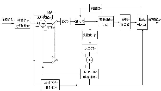
Figure 2.2.3 is a block diagram of MPEG-1 image compression encoder. The binary digitized signals representing the luminance Y and chrominance components CB and CR first enter the frame reorganizer (or frame rearrangement circuit) to divide the picture into slices, macroblocks, and blocks. The block enters the DCT circuit, quantizer, and VLC circuit through the comparison operation circuit to obtain the compressed data. Then send the data to the multiplexer and transmission buffer. The transmission buffer is used to temporarily store compressed data, and output data in time sequence according to the order of control instructions. The buffer is connected to the quantizer through an adjuster (also called quantization adaptor). The adjuster can be used to detect the temporary storage of data in the buffer zone of the buffer, and automatically adjust the quantization step based on the amount of temporary storage data. A feedback path is provided in the encoder, which mainly includes an inverse quantizer (Q-1), an inverse discrete cosine transform (IDCT), an adder, and an IPB frame memory. The feedback loop is used to predict image generation, perform picture classification processing (calculate, distinguish and process IPB pictures), and is mainly used for inter-frame data compression encoding processing. Also, motion prediction and compensation circuits can be used for motion compensation.
2. Image decompression circuit block diagram The image decompression circuit is simply called decompression circuit and decoding circuit. In the VCD video disc machine, after being processed by a digital signal demodulation circuit (CD-DSP), a compressed and encoded video data stream is output, which needs to be decompressed by a video decompression circuit and restored to an uncompressed video signal. The decoding process is the inverse process of encoding. Figure 2.2.4 is a block diagram of the MPEG-1 video decompression circuit. Its circuit structure is slightly simpler than the encoder. 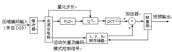
Figure 2.2.4 MPEG-1 video decompression circuit block diagram
The compressed coded signal from the CD-DSP circuit is sent to the input buffer, and then enters the demixing circuit, which separates the image coding mode flag, motion vector (displacement vector) and image data, and is sent to the frame memory and the decompressed main channel circuit, respectively .
The main channel has to process I, P, B frame data. These data have been pointed out by the data packet header according to the regulations of the image coding series. These data are temporarily stored in the storage area of ​​the buffer memory, and there are temporarily different capacities according to the amount of data. In the memory area. Under the control of the microprocessor, the I picture data is first taken out in sequence and sent to the VLC (variable length code demodulator), according to the variable length code comparison table stored in the ROM, the code bits compressed during encoding are restored one by one to The DCT quantization value before compression, and then divide each block into 64 data. The quantization value is multiplied bit by bit by the inverse quantization parameters. These parameters are located in the relative position of the 64-bit visual mental model quantization table stored in ROM, and are restored to the DCT frequency Coefficients to complete the inverse quantization process.
The inversely quantized data is sent to the IDCT (inverse discrete cosine transform) circuit. This is another inverse transform, and also through the table look-up method, the amplitude of each frequency cosine component represented by the inverse quantization value is inversely transformed to restore the sampled data of the image (Y, CB, CR) before DCT transformation, thereby Obtain the representative block information before image compression. The information of 4 blocks forms a macro block, several macro blocks form a slice, and then several slices form the total data of the complete picture, which is the I frame picture. These heavy additions need to be performed in the adder.
The recovered I-frame picture data is stored in the frame memory. The I picture is added to the P picture data input subsequently, the P picture can be restored, and the P picture is also stored in the frame memory. Then according to the difference between the motion vector and the post-motion image (ie B-picture data), the data stored in the I and P pictures are added in the adder, and controlled by the encoding mode signal, so as to determine the number of I and P picture components, thus Restore the B-frame pictures before and after different. The various picture data of I, P, B obtained by the above processing needs to be stored in the buffer memory, and according to the instruction of the encoding mode and the frame rate requirements of the output system, according to I, B, B, P, B, B, P, The normal sequence of B, B ... B, I, B, B, P, B ... is rearranged and output from the frame rearrangement circuit at a certain speed. The output decompressed data is sent to the D / A converter and converted into R, G, and B primary color analog signals.
Usually, a video encoder and a modulator are additionally provided in the decompression circuit. The video encoder can encode the three primary color signals into NTSC / PAL color TV signals, and add synchronization, blanking, color burst, and color subcarrier signals, etc., and output as full analog TV signals. The signal of this output form needs to be delivered to the AV input port of the television receiver. However, some old TV sets do not have an AV input port. In order to adapt to this phenomenon, the output video full TV signal needs to be subjected to high frequency modulation again, and the modulator is used to output the TV signal in the form of RF amplitude modulation of a specific channel. At this time, the VCD machine needs to set the RF output port, and its output signal can be directly sent to the antenna input port of the TV.
DC emergency standby power supply system consists of AC distribution, charging unit, storage battery DC distribution, automatic switching against city grid failed in power supply, etc. It is applied to provide uninterrupted power supply service for the important DC electricity loads.
AC emergency Backup Power Supply system, basing on DC standby power supply, is equipped with single phase (three-phase) DC/AV inverter. It is applied to provide uninterrupted single phase (three-phase) AC power supply service for the important AC electricity loads.
Emergency Power Supply,Led Emergency Power Supply,Emergency Battery Power Supply,Emergency Battery Operation Power Supply
Xinxiang Taihang Jiaxin Electric Tech Co., Ltd , https://www.chargers.be