introduction
MEMS1 (Micro Electro Mechanical System) utilizes manufacturing process facilities developed specifically for semiconductor integrated circuits to achieve manufacturing. The realization method of the microelectromechanical structure is to etch a specific pattern on the semiconductor substrate to realize the sensor unit or a mechanical actuator that can move a few micrometers. MEMS pressure sensors are the first type of mass-produced products. They are now used to monitor the pressure of hundreds of millions of engine manifolds and tires; MEMS accelerometers are used in airbags, roll detection, and car alarm systems. More than 15 years.
MEMS accelerometer 2 is also used for motion sensing in the field of consumer electronics, such as video games and mobile phones. MEMS micromirror optical actuators are used in projectors, HDTVs and digital cinemas. In recent years, MEMS microphone 3 has also begun to enter a broad consumer market, including mobile phones, Bluetooth headsets, personal computers and digital cameras.
This article will discuss some of the key technologies used in MEMS accelerometer products and discuss how these technologies can bring new applications to acoustic sensors.
MEMS accelerometer technology
The core unit of a typical MEMS accelerometer is a movable bar structure consisting of two groups of finger grids: one group is fixed to a physical ground plane on the substrate; the other group is connected to one and mounted to one group On the mass on the spring, the spring can move according to the applied acceleration. The applied acceleration (Figure 1) will change the capacitance between the fixed and moving grid. 4
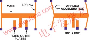
Figure 1: MEMS accelerometer structure.
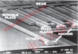
Figure 2: ADXL50 MEMS accelerometer structure.
The size of these MEMS structures is on the order of micrometers (Figure 2), so semiconductor lithography and etching process technologies with extremely high precision are required. MEMS structures are usually formed using single crystal silicon, or polysilicon deposited on the surface of single crystal silicon wafers at extremely high temperatures. With this flexible technology, structures with very different mechanical properties can be formed. One of the mechanical parameters that can be controlled and changed is the spring rate. The mass and structural damping of the sensing unit can also be changed in the design. The sensor can realize acceleration sensing from a few g to hundreds of g, and its bandwidth is up to 20kHz.
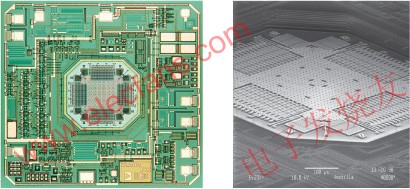
Figure 3: ADXL202 ± 2 g accelerometer.
MEMS sensing units can be connected to signal conditioning circuits located on the same chip (Figure 3) or on different chips (Figure 4). For a single-chip solution, the capacitance of the sensing unit can be as low as 1-2 femtofarads per g, which is equivalent to a measurement resolution of 10-18F! In a two-chip architecture, the capacitance of the MEMS unit must be high enough to Overcome the influence of parasitic capacitance of the connecting line between MEMS and ASIC conditioning circuit. 5
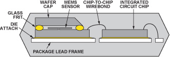
Figure 4: A cross-sectional view of a typical two-chip accelerometer.
Accelerometer as a vibration measurement sensor
The concept of using vibration sensor sensors to pick up sound in musical instruments is not new. 6 Piezoelectric and electromagnetic sensors are the basis of many acoustic pickup applications today. Because the miniature MEMS accelerometers are small in size and mass, they do not affect the instrument in terms of mechanical or mass loads, making them attractive in these applications. But so far, due to the narrow bandwidth of commercial acceleration sensors, its application is still relatively limited.
Some recent breakthroughs in accelerometer technology have resulted in mass production of very small accelerometers with very high bandwidth. The ADXL0017 (Figure 5) high-g (± 70g to ± 500g) single-axis accelerometer in a 5mm × 5mm × 2mm package has a bandwidth of up to 22kHz, making it ideal for monitoring vibration. The motor can be determined by detecting changes in the device ’s acoustic characteristics Or “health†status of other industrial equipment. In the early stages of bearing wear, a high-g vibration sensor attached to the system base can detect a clear vibration signal in the audio range. This special sensor used to measure up to 10g is obviously not sensitive enough to be used as an acoustic vibration sensor for musical instruments. The ideal acoustic sensor needs to measure the response in all three axes, but it can only sense single-axis motion. However, it has been proved that using MEMS technology can already achieve acceleration sensors within the full audio bandwidth.
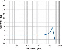
Figure 5: Frequency response curve of ADXL001.
Low-g accelerometers can measure accelerations down to the g-thousandth of a g, but the bandwidth is generally limited to about 5 kHz. In fact, the reason for this limitation may be that there are too few commercial applications that require high bandwidth (main applications include acceleration detection caused by human motion or gravity), so there is a lack of motivation to develop sensors that are particularly suitable for audio frequency band measurement.
A 3-axis accelerometer has three independent outputs that measure the acceleration on the X, Y, and Z axes in Cartesian coordinates. The ADXL3308 3-axis low-g accelerometer has a wider effective bandwidth than traditional low-g accelerometers. Its bandwidth is up to 6 kHz on the X and Y axes, and around 1 kHz on the Z axis. Although not ideal, this bandwidth has enabled the device to obtain useful information on the audio segment. The output is an analog signal, so it is easy to use in standard recording equipment. The device uses a standard surface mount package, making full use of mature semiconductor manufacturing equipment. The package size is 4mm × 4mm × 1.45mm (Figure 6), which can be applied to places that are incredible for traditional accelerometer technology. Its volume is very small and will not cause changes in the mass load or other aspects of the system under test. The following will explain why the low-g accelerometer can be used for acoustic pickup applications of guitars.
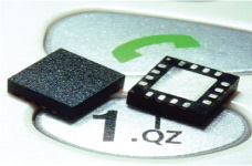
Figure 6: MEMS accelerometer, package size is 4mm × 4mm × 1.45mm.
Voice feedback problem
Danish scientist Soren Larsen first introduced an omnidirectional condenser dynamic microphone in the mid-nineties of the last century. It was the earliest discovery of the principle of sound feedback (called the Larsen effect). Acoustic feedback has always been a nightmare for acoustic engineers. Few engineers have complete control over it, especially at any performance scene. The Beatles fully felt the impact of this false sound, and then decided to add it to the introductory song of their memorable album "I Feel Good" in 196410. Then Rock 'n' Roll began to use it like a taming beast, using voice feedback to add a refreshing feature to rock music. Electric guitar players, such as Pete Townshend and Jimi Hendrix, deliberately placed the guitar close to the speaker to use acoustic feedback. As this trend subsided, audio engineers continued to work hard to eliminate the unpleasant auditory effects caused by sound feedback, especially during live performances. In an audition room that is perfectly designed and treated with special acoustics, omnidirectional microphones can be used to perfectly record instrument sounds, almost reaching an amazing sense of presence and fidelity. Artists who understand and cherish this point have been tirelessly seeking how to reproduce this effect on the stage. Although hoping to record live performances in the same quality as the studio has always been the dream of musicians, it is actually impossible. Even if the best sound equipment is used on the stage, the stage has undergone excellent acoustic design. Sound engineers can use all kinds of reverberation proficiently and can have the best equipment and tools. There are insurmountable obstacles: that is voice feedback.
Acoustic pickup
Generally, the use of directional microphones can minimize sound feedback. To some extent this is possible, but it requires tuning engineers to constantly adjust to the changing characteristics of the stage.
Use the pickup to amplify the sound of the instrument. The various technologies used have certain differences, but the basic principle is to directly sense the vibration of the instrument itself, rather than detecting the sound waves it generates in the air. The advantages of this approach are obvious: pickups hardly produce sound feedback because they are not sensitive to the sound waves transmitted in the air. But this method also has many shortcomings: including finding the best sound position on the instrument is extremely difficult, the acoustic characteristics of piezoelectric pickups are far from perfect, and their output impedance is high impedance, so special Musical instrument input or direct boxes. In addition, the volume is also large, which will affect the natural acoustic characteristics of the instrument itself.
Thus, these problems led to the concept of low-quality contact microphones. If we use a surface sensor to measure the acceleration of the instrument body, this is more suitable than a single axis. 11 This sensor has better linearity and lighter weight, so that it will not affect the sound characteristics of the instrument under test. It can be further assumed that these sensors have similar output levels, output impedances, and required power comparable to traditional microphones. In short, it is assumed that the musician can insert the sensor into the microphone preamplifier or mixer input, 12 like any other microphone.
Contact microphone
We have already mentioned the concept of acceleration before. The human ear responds to sound pressure, so the microphone is also designed to sense sound pressure. To simplify the discussion, here is a conclusion that the sound pressure near a vibrating body is proportional to the acceleration. The question is how high a bandwidth the accelerometer can be used as a contact microphone?
In order to study the concept clearly, a 3-axis accelerometer was attached to the guitar as a pickup. The vibration of the instrument is measured and compared with the built-in piezoelectric pickup and the MEMS microphone near the guitar. The guitar used is Fender StratacousTIc with a built-in Fender pickup. A MEMS accelerometer with analog output is mounted on a very light-weight flexible circuit (polyimide with etched leads), and it is mounted on the bridge position of the guitar with beeswax, as shown in Figure 7. The X axis of the accelerometer is aligned with the guitar string, the Y axis is perpendicular to the guitar string, and the Z axis is perpendicular to the guitar surface. Install a MEMS microphone with a flat frequency response of 15kHz to a position 3 inches away from the string as a reference.
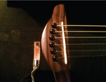
Figure 7: Accelerometer installed on Fender StratacousTIc guitar.
Using the accelerometer, built-in piezoelectric pickup and MEMS microphone each recorded a sound. Figure 8 shows the time-domain waveforms of each sensor. There is no post-processing of any segments.
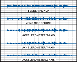
Figure 8: Time-domain waveforms using different sensors.
Fig. 9 shows the FFT spectrum of the piezoelectric pickup measured at a peak of the above-mentioned time-domain waveform. The results show that the response has a strong bass component. Indeed, there are many bass responses in actual audio files. This sound is more pleasing (also depends on personal preference), because cavity resonance can produce richer bass than directly heard from the instrument.
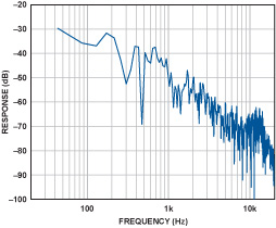
Figure 9: Spectrum of a piezoelectric pickup.
The output of the MEMS microphone is very flat, and the reproduction of musical sound is very good. The sound quality is very natural, well balanced, and high fidelity. The FFT spectrum measured at the same time as the piezoelectric pickup is shown in Fig. 10 (a). For reference, Figure 10 (b) shows the frequency response of the MEMS microphone.
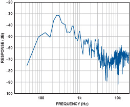
Figure 10 (a): Spectrum of MEMS microphone.
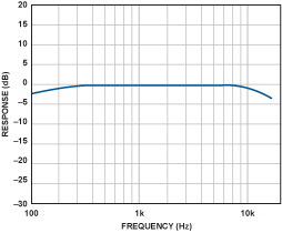
Figure 10 (b): Frequency response of MEMS microphone.
The output of the MEMS accelerometer is very interesting. The current shortcomings include the noise floor is too high, can be heard at the beginning and end of the audio track, and the Z-axis bandwidth is significantly limited to lower frequencies. The sound reproduction in each axis is also significantly different.
The sound on the X-axis and Y-axis is bright and clear, and there are obvious differences in tone. As expected, the sound on the Z axis is clearly mainly bass. Fig. 11 (a), (b) and (c) show the frequency spectra on the X, Y and Z axes respectively.
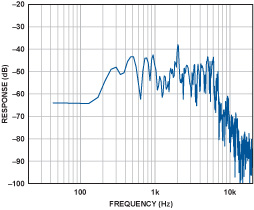
Figure 11 (a): Spectrum on the X axis.
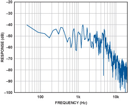
Figure 11 (b): Spectrum on the Y axis.
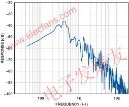
Figure 11 (c): Spectrum on the Z axis.
If the X, Y and Z axes are mixed together, a better reproduction of the musical sound can be achieved with a certain degree of clarity. By adjusting the mixing process, the tone balance can be changed to achieve natural music reproduction. Due to the current bandwidth limitation of the accelerometer, a larger range of high-frequency harmonics are lost, but the sound reproduction is still surprisingly realistic.
Conclusion
The low-g MEMS accelerometer does not have the traditional sound feedback problem, and can be used as a high-quality pickup for musical instruments, with obvious application potential. The above experimental results show that a 3-axis accelerometer attached to the Fender StratacousTIc guitar can achieve good musical reproduction. Because the vibration mode of the instrument body is different in different directions, the sound characteristics of the three axes of the accelerometer related to it are also different. Mixing the three channel outputs can reproduce the original sound effect. In addition, mixing the sound of these channels in different ways can produce creative sound effects.
In this experiment, although the application prospect is good from the performance of the accelerometer, there are some shortcomings, such as being able to hear the sensor's base noise, but the effect of this problem can be minimized by using noise gating or other techniques And the noise floor of an ideal sensor will be similar to that of a traditional microphone. The high-frequency response of the sensor needs to be expanded, ideally to reach 20kHz, so that it can cover the entire audio range of the instrument.
MEMS accelerometer technology has obvious potential advantages in the application of musical instruments, especially those field applications that are troubled by sound feedback problems. A very small, low-power MEMS device can be attached to any inconspicuous position in the instrument without affecting the natural vibration characteristics of the instrument. In fact, several sensors can be placed on different positions of the instrument to provide additional flexibility for acoustic engineers to reproduce the natural characteristics of the instrument without worrying about the sound feedback of the live application, so it can be said that the distance is "ideal music" Only one step away!
Integrated Solar Street Light with lithium battery motion sensor integrated street light,called all in one intergrated Solar Street Light which integrates the green energy parts solar panel, LED lamp and Lithium Battery into a single product, with human intelligence induction system to control the lighting mode automatically.
Our all in one intergrated Solar Street Lights use USA Cree Chips with High Brightness, IP65 waterproof, we can produce the All In One Solar Street Light from 12W to 120W.

Integrated Solar Street Lights
Integrated Solar Street Lights,Led Integrated Solar Street Light,Integrated All In One Solar Street Light, Solar Powered Integrated Street Light
Yangzhou Bright Solar Solutions Co., Ltd. , https://www.cnbrightsolar.com