1. Introduction to TIM of STM32
STM32 microcontrollers come with a total of 11 timers, including 2 advanced control timers, 4 general-purpose timers, 2 basic timers, and 2 watchdog timers along with the system timer (SysTick). The SysTick timer was discussed in the previous section, while the watchdog timer will be covered in detail later. Today’s focus is on the remaining 8 timers.
| Timer | Counter resolution | Counter type | Prescaler coefficient | Generate DMA request | Capture/compare channel | Complementary output |
| TIM1 TIM8 |
16 bits | Up, down, up/down | Any number between 1-65536 | Yes | 4 | Yes |
| TIM2 TIM3 TIM4 TIM5 |
16 bits | Up, down, up/down | Any number between 1-65536 | Yes | 4 | No |
| TIM6 TIM7 |
16 bits | Up | Any number between 1-65536 | Yes | 0 | No |
Among these, TIM1 and TIM8 are advanced timers capable of generating three pairs of PWM complementary outputs, commonly used for driving three-phase motors. Their clock is sourced from APB2. TIM2-TIM5 are general-purpose timers, while TIM6 and TIM7 are basic timers that use APB1 as their clock source. Due to the complexity of the TIM functionality in STM32, we will start from the basics—focusing on the timing function of TIM2-TIM5.
2. Basic Timer TIM6-TIM7
2.1 Clock Characteristics
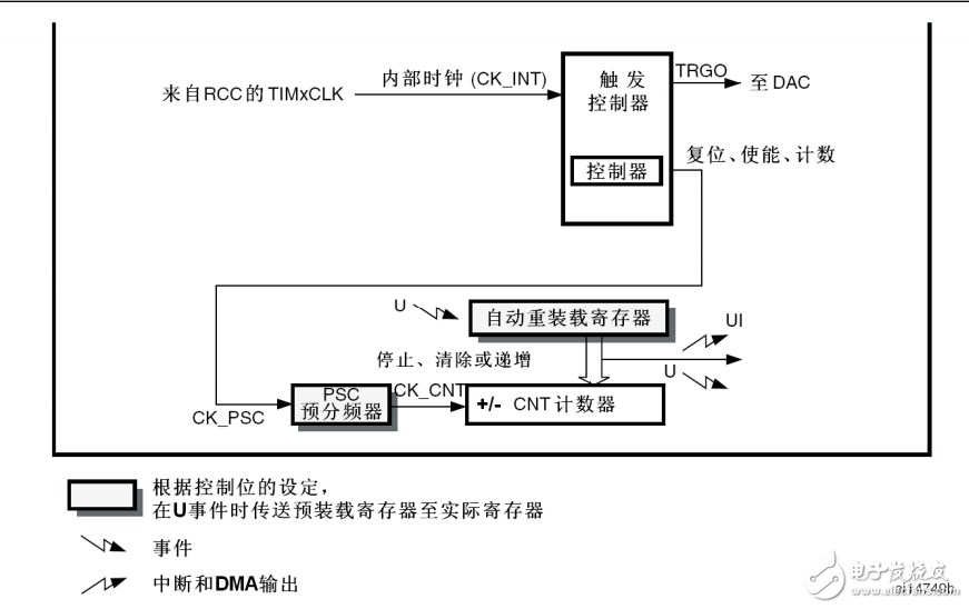
The basic timers TIM6 and TIM7 each have a 16-bit auto-reload counter driven by a programmable prescaler. They serve as general-purpose timers, often used to provide a time reference for digital-to-analog converters (DACs). These timers are directly connected to the DAC inside the chip and can trigger the DAC through a dedicated output. TIM6 and TIM7 are independent of each other and do not share any resources.
2.2 Main Features of TIM6-7
The main features of TIM6 and TIM7 include:
- 16-bit auto-reload counter
- 16-bit programmable prescaler for any value between 1 and 65536
- Synchronous circuit to trigger the DAC
- Generate interrupt/DMA request during an update event (counter overflow)
Figure 144 shows the block diagram of the basic timer.
2.3 Counter Mode
TIM6 and TIM7 operate in up-counting mode. In this mode, the counter counts from 0 to the auto-reload value (TIMx_ARR), then resets to 0 and generates an overflow event.
2.4 Register Details for TIM6-TIM7
1. TIM6 and TIM7 Control Register 1 (TIMx_CR1):
- ARPE: Auto-reload preload enable (0: no buffer, 1: buffered)
- URS: Update request source (selects which events generate an update interrupt or DMA request)
- UDIS: Update disabled (0: enabled, 1: disabled)
- CEN: Counter enable (0: disabled, 1: enabled)
2. TIM6 and TIM7 Control Register 2 (TIMx_CR2):
3. TIM6 and TIM7 DMA/Interrupt Enable Register (TIMx_DIER):
- UDE: Update DMA request enable
- UIE: Update interrupt enable
4. TIM6 and TIM7 Status Register (TIMx_SR):
- UIF: Update interrupt flag (set when an update occurs, cleared by software)
5. TIM6 and TIM7 Event Generation Register (TIMx_EGR):
- UG: Generate update event (reinitializes the counter and updates registers)
6. TIM6 and TIM7 Counter (TIMx_CNT):
- CNT[15:0]: Current counter value
7. TIM6 and TIM7 Prescaler (TIMx_PSC):
- PSC[15:0]: Prescaler value (CK_CNT = f_CK_PSC / (PSC + 1))
8. TIM6 and TIM7 Auto-reload Register (TIMx_ARR):
- ARR[15:0]: Auto-reload value (if set to 0, the counter stops)
2.5 Programming Steps
1. Configure the priority;
2. Enable the clock;
3. Configure GPIO;
4. Configure TIM;
5. Enable the counter;
6. Enable the interrupt;
7. Clear the flag bit;
The specific configuration includes:
- NVIC_Configuration(); // Set interrupt priority
- RCC_APB2PeriphClockCmd(RCC_APB2Periph_GPIOC, ENABLE); // Enable clock
- GPIO_Init(GPIOC, &GPIO_InitStructure); // Configure GPIO
- TIM_Configuration(); // Configure TIM6/TIM7
- TIM_Cmd(TIM7, ENABLE); // Enable timer
- TIM_ITConfig(TIM7, TIM_IT_Update, ENABLE); // Enable interrupt
- TIM_ClearFlag(TIM7, TIM_FLAG_Update); // Clear flag
In step (4), the prescaler coefficient determines the timer's clock frequency. The formula is CK_INT/(TIM_Prescaler+1). CK_INT is the internal clock frequency, derived from APB1. TIM_Prescaler is the user-defined value ranging from 0 to 65535.
The clock division setting in step (4) defines the timer clock frequency (CK_INT) and the sampling frequency for digital filters (ETR, TIx). The parameters of TIM_ClockDivision are as follows:
| TIM_ClockDivision | Description | Binary Value |
| TIM_CKD_DIV1 | tDTS = Tck_tim | 0x00 |
| TIM_CKD_DIV2 | tDTS = 2 * Tck_tim | 0x01 |
| TIM_CKD_DIV4 | tDTS = 4 * Tck_tim | 0x10 |
It is important to disable the preload buffer in step (4). When the preload buffer is disabled, the value written to the auto-reload register (TIMx_ARR) is directly passed to the shadow register. If enabled, the value is updated only when an event occurs.
In ARM architecture, some registers have two physical registers: a preload register (accessible to the programmer) and a shadow register (used internally). This design ensures accurate synchronization of multiple channels. Without it, updates may be inconsistent due to timing issues, especially when interrupts are involved.
3. Program Source Code
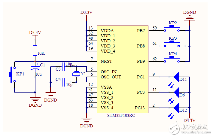
This example uses the TIM7 timer to make an LED flash every second.
Schematic:
/*
* File name: main.c
* Description: Create a project from scratch, use button 1 to trigger interrupt 1 to make LED 1 blink, and button 2 to trigger preemption interrupt 1 to make LED 2 blink.
* Two LEDs: PC3 and PC1
* Output 0 turns on the LED
* Output 1 turns off the LED
* Buttons: PB7 and PA11
*/
#include "stm32f10x.h"
/* Delay function */
void Delay(__IO uint32_t nCount)
{
for(;nCount != 0; nCount--);
}
/* GPIO configuration function */
void GPIO_Configuration(void)
{
GPIO_InitTypeDef GPIO_InitStructure;
RCC_APB2PeriphClockCmd(RCC_APB2Periph_GPIOC, ENABLE);
GPIO_InitStructure.GPIO_Pin = GPIO_Pin_3;
GPIO_InitStructure.GPIO_Mode = GPIO_Mode_Out_PP;
GPIO_InitStructure.GPIO_Speed = GPIO_Speed_50MHz;
GPIO_Init(GPIOC, &GPIO_InitStructure);
}
/* Configure NVIC priority */
void NVIC_Configuration(void)
{
NVIC_InitTypeDef NVIC_InitStructure;
NVIC_PriorityGroupConfig(NVIC_PriorityGroup_0);
NVIC_InitStructure.NVIC_IRQChannel = TIM7_IRQn;
NVIC_InitStructure.NVIC_IRQChannelCmd = ENABLE;
NVIC_InitStructure.NVIC_IRQChannelPreemptionPriority = 0;
NVIC_InitStructure.NVIC_IRQChannelSubPriority = 0;
NVIC_Init(&NVIC_InitStructure);
}
/* Timer initialization */
void TIM_Configuration(void)
{
TIM_TimeBaseInitTypeDef TIM_TimeBaseStructure;
TIM_TimeBaseStructure.TIM_Prescaler = 36000 - 1;
TIM_TimeBaseStructure.TIM_ClockDivision = 0;
TIM_TimeBaseStructure.TIM_CounterMode = TIM_CounterMode_Up;
TIM_TimeBaseStructure.TIM_Period = 2000 - 1;
TIM_TimeBaseInit(TIM7, &TIM_TimeBaseStructure);
TIM_Cmd(TIM7, ENABLE);
TIM_ITConfig(TIM7, TIM_IT_Update, ENABLE);
}
/* Main function */
int main(void)
{
GPIO_Configuration();
NVIC_Configuration();
TIM_Configuration();
while(1);
}
/* TIM7 interrupt handler */
void TIM7_IRQHandler(void)
{
if(TIM_GetITStatus(TIM7, TIM_IT_Update) == SET)
{
GPIOC->ODR ^= GPIO_Pin_3;
TIM_ClearITPendingBit(TIM7, TIM_FLAG_Update);
}
}
Programming Experience:
1. Remember to enable the timer with TIM_Cmd(TIM7, ENABLE), enable the interrupt with TIM_ITConfig(TIM7, TIM_IT_Update, ENABLE), and enable the clock with RCC_APB1PeriphClockCmd(RCC_APB1Periph_TIM7, ENABLE).
2. Always clear the interrupt flag with TIM_ClearITPendingBit(TIM7, TIM_FLAG_Update) after entering the interrupt service routine.
Linear Amplifiers Instrumentation OP Amps
Linear Amplifiers Instrumentation Op Amps,Chips Linear Amplifiers Instrumentation,Ic Linear Amplifier Instruments,Linear Amplifiers Instrumentation
Shenzhen Kaixuanye Technology Co., Ltd. , https://www.icoilne.com