The Application of XBee Pro Module Based on ZigBee Technology in Intelligent Bus System
With the rapid development of the domestic economy, the size of the city is constantly expanding, especially the rapid growth of various modes of transportation, so that the contradiction between urban transportation demand and supply is increasingly prominent, and the expansion of road transportation infrastructure alone to ease the contradiction The practice is unsustainable. In this case, the Advanced Public Transport System (APTS) has emerged at the historic moment, and has become a hot spot for domestic research in recent years. Among the various technologies involved in the intelligent bus system, wireless communication technology is particularly noticeable. ZigBee, as an emerging short-range, low-rate wireless communication technology, has received more and more attention and application. At present, a large number of various products related to ZigBee have appeared on the market. Among them, the more competitive ZigBee solutions mainly include the following:
(1) Freescale: MC1319X platform;
(2) Chipcon: SoC solution CC2430;
(3) Ember: EM250ZigBee system chip and EM260 network processor;
(4) Jennic's JN5121 chip;
After market research, it was found that Freescale's MC1319X platform has low power consumption, low price, high hardware integration, easy secondary development, and high stability of the RF communication system. Therefore, in the design of this article, the XBee Pro RF module with Maxscale and ZigBee compatible with Freescale MC1319x chipset as the core is selected. The following mainly introduces Xbee Pro's features, interface applications, operation modes, and applications in the wireless network of intelligent public transportation.
1 XBee Pro module features and interfaces
The basic performance parameters of the XBee module are as follows:
(1) Transmission power: 100 mW;
(2) Receive sensitivity: -92 dBm;
(3) The indoor transmission distance is 100 m, and the outdoor transmission distance is 1500 m;
(4) The RF data transmission rate is 250 kbps;
(5) Under the 3.3 V power supply, the sending current is 215 mA and the receiving current is 55 mA:
(6) In terms of network performance, it has DSS (direct sequence spread spectrum) function, which can form peer-to-peer, point-to-point and point-to-multipoint networks, with 12 software-selectable direct sequence channels, each channel has 65 000 Available network addresses.
The XBee Pro module is small in size, low in power consumption, simple in interface, and easy to use. It is very suitable for short-distance communication applications with low data rates, especially the design and application of wireless sensor networks. The XBeePro module also provides free X-CTU test software to enable easy testing and configuration of the network. The module can also download the company's latest firmware (Firmware), so that users can use the original hardware module based on the latest features, thus providing great flexibility for the design.
Figure 1 shows the pin diagram of the XBee Pro module. Xbee Pro has 20 pins. Among them, VCC, GND, DOUT and DIN in the pins are used to connect the pins of the circuit board with the RS232 interface. The VCC pin is a power supply pin, ranging from 2.8 to 3.4 V; GND is the ground pin; the signal direction of the DIN pin is the input, used as the data input of the UART, and is usually connected to the TX of the UART receiving end of the processor; the DOUT pin signal The direction is output, as UART data output, usually connected to the UART receiver RX of the processor. The version of fimrwaer released by MaxStream does not currently support the functions of pins ADO-AD5, DIO0-DIO7 and DO8. 
There is a UART interface integrated in the XBee Pro module, and its internal structure is shown in Figure 2. 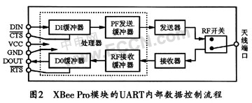
When serial data enters the XBee Pro module through the DIN pin, the data will be stored in the DI buffer until it is sent by the transmitter through the antenna; when the antenna receives RF data, the received data will first enter the DO buffer, and then Then serially sent to the host. Under certain conditions, the module may not be able to immediately process the data in the serial receive buffer. At this time, CTS flow control is needed to avoid the problem of overflow of the receive buffer caused by a large amount of serial data input. The XBee Pro module can be directly connected to the UART interface of the controller through the UART interface, and its hardware interface is very simple and practical.
2 Operation mode of XBee Pro module
XBee Pro has 5 operation modes including empty mode, receiving mode, sending mode, sleep mode and command mode, as shown in Figure 3. Each operation mode has two operation modes: transparent mode and application program interface (API) mode. When working in the transparent mode, the module can play the role of replacing the serial port line and process various information in bytes; when working in the API mode, all data entering and leaving the module are included in the operation and definition of the module Event frame structure. This design adopts API operation mode. 
API operation requires a structured interface (data is communicated through a defined sequence of frames to communicate with each other) to communicate. At the same time, the API specifies how to send commands, command responses, and the transmission and reception of module status information through serial data frames.
3 Application of XBee Pro module in intelligent bus system
There are usually multiple buses arriving at the stop sign at the same time, and one stop sign corresponds to multiple buses. It is suitable for using a star network wiring network. However, in order to ensure the reliability of the network, when the passage outside the bus stop is blocked, it can be forwarded to the stop through other bus routing nodes. This design uses a mesh network model. The electronic stop signs distributed on the bus line can be configured as a coordinator, and the arriving bus can be configured as a router. When the ZigBee network coordinator on the stop sign selects a channel and PAN ID and starts up, a ZigBee personal office network (PAN) is established. Once the coordinator has started the PAN, the router and end device nodes can be allowed to join the PAN. When the router joins the PAN, it will receive a 16-bit network address and be able to send and receive data from other devices in the PAN. The network address of the PAN coordinator is always 0. Because the network physical address of the ZigBee module on the stop sign is unique, you can send information to the stop sign through the physical address.
After the bus arrives at the stop sign, the date, time, bus number, bus line, number of people in the car, driving direction and other information are sent to the electronic stop sign according to the MAC address of the stop sign. The definition of the API frame structure of the sending mode of the bus ZigBee module is shown in Figure 4.
In order to achieve reliable transmission, when the request for the bus to send information to the electronic stop sign is completed, the information confirmation information of the electronic stop sign must be obtained, so the sending status information that the electronic stop sign is fed back to the bus must also be obtained. This information will indicate whether the packet was successfully sent. If the transmission fails, the bus information must be re-sent until the transmission is successful. Figure 5 shows the status frame structure of TX. Among them, Bytes 9 indicates the transmission status information, and Bytes 6 and 7 are the 16-bit network address of the receiving module.
The definition of the API frame structure of the receiving mode of the electronic station brand ZigBee module is shown in Figure 6. 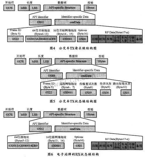
You can configure the command parameters through the configuration software X-CTU provided by the XBee Pro module, or you can enter the command mode by entering "+++" to configure. The command format of the XBee Pro module is as follows:
AT ASCIlI command space parameter (optional) Enter
Table 1 lists the parameter settings for the ZigBee module of the electronic stop sign terminal. 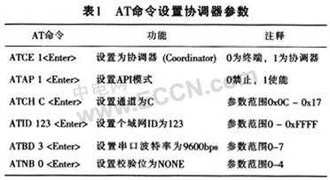
The ZigBee module of the bus must be set to the router (Rooter) mode, and the channel and PAN ID should be the same as the electronic stop sign settings. After testing, the system is stable.
4 Conclusion
This article introduces the performance characteristics of MaxStream's Xbee Pro module compatible with ZigBee / IEEE802.15.4 protocol and its application in the wireless communication of intelligent bus system. Currently, the company's mesh firmware version for Xbee Pro modules has greatly enhanced its networking capabilities. With the popularity of ZigBee technology, Xbee Pro modules will also be more widely used in wireless sensor networks.
RS232 Wireless Modem is used to replace wired RS232 serial communication cables. PufangTech`s RS232 Wireless Modem can establish a transparent radio serial connection between point to point or among point to multi-point stations in half duplex mode.
The wireless modem has a robust range of 1 to 10Km through buildings and up to 50Km line of sight without any special antenna configurations. It transmits and receives RS232 data at interface baud rates of 1200bps to 115200bps. The low cost unit operates on VHF/UHF frequency band and is modulated with narrow band digital FM.
It can be used in any remote supervision and control applications such as master stations of oil, gas and water pipelines, environmental monitoring, street light control, wastewater pumping stations and OEM applications.
RS232 Wireless Modem
RS232 Wireless Modem,Wireless RS232,RF Modem RS232,RS232 Wireless GSM Modem
Shenzhen PuFang Technology Co., Ltd. , https://www.hytelus.com